Hello,
I am having an issue with the my trigger for the ChipShouter. I have included a diagram of the signals from my oscilloscope below. I want to glitch a microcontroller. I use an IO pin as a trigger (shown by the green signal D0) which I set high before executing a few instructions and then low again after. I also measure the internal clock from the MCU (shown in red, D1). Both of the signals were measured with digital channels on my oscilloscope. I am using a Husky as a trigger for my ChipShouter; the “Trigger/Glitch Out (3.3V)” output connected to the ChipShouter’s trigger input. I have the parameters for the Husky and the ChipShouter in images below. When the measurement in the diagram was taken, the ChipShouter was placed far away from the chip, so that the EM field would not affect it. I did this to test my setup to see if everything was working as expected without faults in the MCU. Unfortunately, sometimes my trigger and clock signals become zero for short periods of time (as shown in the diagram). I have taken lots of measurements with different voltages and trigger lengths. This does not happen on all measurements but it does sometimes. This is a problem because the effect it has on the clock is essentially a clock glitch. However, I want to test only the effect of EMFI on the MCU and not a clock glitch that is coming from some other place within the setup. I have tried out many different parameters and have not been able to get rid of this effect. Have you noticed this issue? Do you have any suggestions on how to fix it?
I hope I have provided all necessary information. Please let me know if anything is unclear. Thanks in advance for any help.
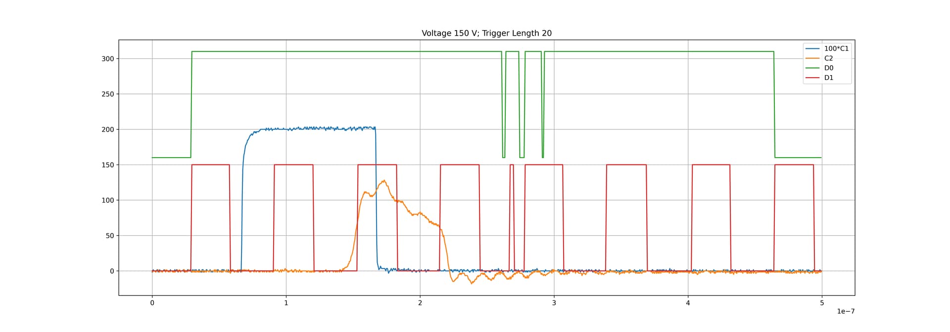
Here is a diagram of the signals measured with the scope. I C1 is HS2 signal from the Husky measured from the “Aux In/Out (3.3V)” output and the oscilloscope is set to 50 Ohms when I measured it. C2 is the signal from the ChipShouter (the channel was set to 1 megaohm).
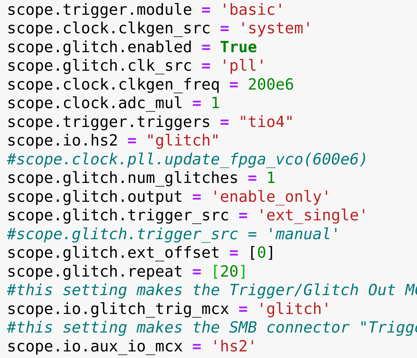
These are the parameters on the Husky:
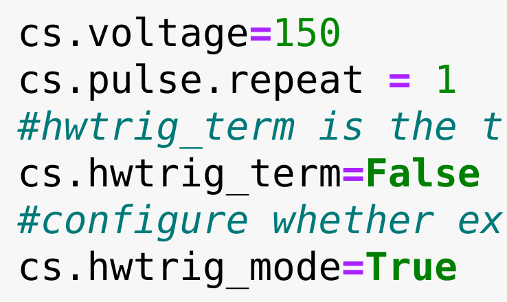
These are the parameters for the ChipShouter: