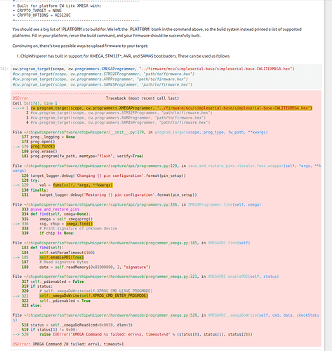
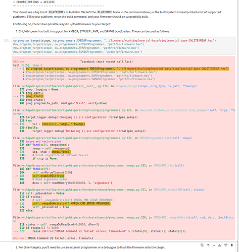
I have purchased a new CW Lite with XMEGA target board and followed the instructions. I made it to Tutorial 1 Connecting to Hardware, and built the target firmware without an issue. However, trying to upload to the target board gives this error every time:
Based on similar posts I have tried:
-using ‘scope.dis()’ and ‘target.dis()’ along with physically reconnecting, resetting Jupyter and all notebook blocks, etc. - basically ensured it wasn’t in error mode as it was for others with this problem
-I have confirmed filepath, moreover using incorrect filename yields the same error implying it can’t even connect to the target board
-the Red/Green LEDS are ON for the target board, meaning it’s connected and powered
-I tried the tip from similar posts involving shorting JP6/7 to power (or whatever that one was)
-CW version is 5.7.0 - one post suggested switching to develop branch, I followed the instructions to do so (and git says I’m on that branch) but ‘cw.version’ still prints 5.7.0
-default scope settings used
Is it possible there is a hardware fault with the XMEGA target board, as one post mentioned this has happened?
Are you sure you’re not running into this? Your screen capture shows this is cell #74 - can you re-try with a totally clean slate?
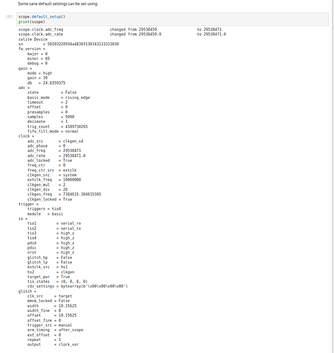
Other things to try are different USB cables and ports. Also, are you able to communicate with ChipWhisperer: what does print(scope) show?
I restarted the kernel and cleared all outputs/variables to be sure, in addition to disconnecting and reconnecting:
The output of print(scope) is shown below:
I’m not sure what I’m still doing wrong?
Can you copy/paste (as text) the output of your make command?
And don’t forget to try different USB ports and cables.
This is the most recent one (the hex file was made during the first attempt - if it helps I can delete and redo the command from scratch for full output):
I threw in an ‘ls’ so you can see that the hex file is present:
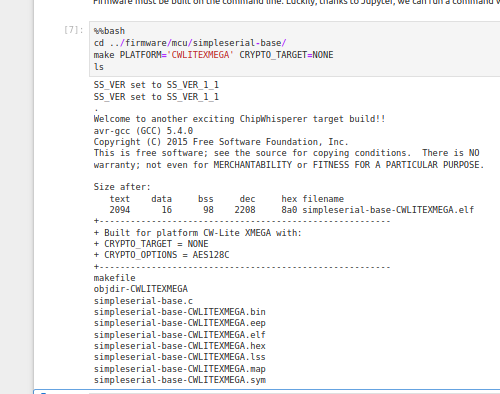
By the way thanks so much for the quick responses! :]
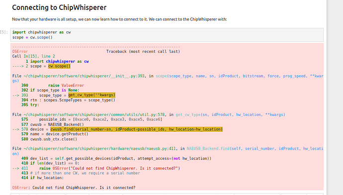
*also tried a different USB port with no difference. Trying a bad USB cable I got this error right away, so it seems the cable NewAE provided was working:
Hi,
Do you mean LEDs 9 and 10 on the target side of the board are on? If so, the microcontroller’s at least alive. Do you have access to a multimeter?
Correct, LED’s 9/10 are on when plugged in. I do have a multimeter handy
Can you try setting scope.io.pdic/pdid high/low and seeing if those settings are reflected in the actual IO level on the target side of the board?
This test was successful - switching between high/low I see pins changing between ~1.33/0V on both the scope and target side
I’m not too sure then; there’s nothing wrong with the connection between the FPGA and the Xmega. There might be something wrong with the connection between the SAM3U and the FPGA, but that would be harder to diagnose. We might just have to ship the unit back here for further diagnosis. Can you contact support@newae.com so that we can make that happen?
No problem, just emailed support. Thanks again for your help! 
