Hello,
I am currently glitching an 8051 device to do a jump from internal ROM to external program space (EEPROM) with my own code in there. I’ve been at it for weeks doing voltage glitching with few results.
A few days ago I tried clock glitching and again was getting almost no results. I verified with the oscilloscope that the glitches were happening according to the settings (width, repeat, offset, ext_offset) but there was no reaction from the target.
However, while I was faffing with the connections between the target and the CW-Lite, I suddenly had successful glitches and was able to take limited control of the chip. However, the glitch parameters didn’t seem to have any commonality - they were all over the place. I then suspected some float somewhere as the “glitches” were happening even when I wasn’t arming the CW for the glitch! (they weren’t glitches generated by CW)
After a few more closer looks at the wiring I realised that my ground from target to CW via the SMA port was somewhat loose. And the tiniest of wiggles caused the “glitch”.
The setup is:
- Target powered by external power supply
- Clock generated by CW and is fed to the target (with an option to switch to external crystal derived clock)
- Serial pin on 8051 connected to TX in on the CW (allows me to monitor activity on the target)
- nRst on CW connected to RST on target
- Glitch SMA connected to target’s 5V and ground - largely for ground connection
scope.clock.adc_src = "clkgen_x1"
scope.clock.clkgen_freq = 11.059E6

scope.glitch.clk_src = "clkgen"
scope.glitch.output = "clock_xor"
scope.glitch.trigger_src = "ext_single"

scope.trigger.triggers = "tio4" # This is connected to nRst pin to trigger on reset (not sure if there's a better way)

scope.io.hs2  = "glitch"
scope.io.glitch_hp = False
scope.io.glitch_lp = False
Observations:
- When the target’s clock is generated by the onboard crystal, it never glitches when fiddling with the ground connection
- The glitch settings don’t seem to matter when the target is driven by CW’s clock
- The glitch /sometimes/ happens when fiddling with the clock pin
It seems to me that there has to be a substantial jitter on the clock line to make the target misbehave in a desired manner and that seems to be the ground connection between the target and CW. So my thinking is that the CW isn’t generating a jittery enough clock. Perhaps it needs to be out of phase with the source clock, faster clock or something else that cannot be achieved natively.
What are my options here? Would slowing or speeding up the target help in my case? The target can run on between 2MHz and 16MHz clock. clkgen_x1 vs clkgen_x4 ? Can I do a mixed clock/voltage glitch with CW-Lite? I think the closest I can get to this is to generate a voltage glitch while the clock is being generated by CW, which I think is setting scope.io.hs2 = "clkgen"?
Any other advice/suggestions would be much appreciated.
From your description, I would guess that your target isn’t using your glitchy clock directly to drive its internal logic, but instead feeds it to a PLL which then generates the internal clock. A side-effect of this is that PLLs are very effective at cleaning up glitches. This doesn’t mean that clock glitching is impossible, but it does generally make it a LOT harder. Search the literature for “glitching through a PLL” to learn more.
Usually, this means that voltage glitching or EMFI is a better approach.
You should usually be able to confirm the PLL hypothesis from the target’s datasheet. Sometimes the datasheet will tell you how to bypass the PLL.
Voltage glitching didn’t yield any practical results but will try again.
There’s nothing in the datasheet that mentions PLL except
XTAL1 and XTAL2 are the input and output, respectively, of an inverting amplifier. The pins can be configured for use as an on-chip oscillator, as shown in the logic symbol, page 3. (page 3 shows external crystal connected to pins 18 and 19).
To drive the device from an external clock source, XTAL1 should be driven while XTAL2 is left unconnected. There are no requirements on the duty cycle of the external clock signal, because the input to the internal clock circuitry is through a divide-by-two flip-flops.
I never disconnected XTAL2 pin from the external crystal so does that mean that it’s a form of PLL?
No, but this:
the input to the internal clock circuitry is through a divide-by-two flip-flops.
is telling you that the ChipWhisperer’s glitchy clock doesn’t directly clock the internal logic. This divide-by-two flop won’t filter out glitches the way a PLL would, but it will change the glitch characteristic.
Based on what you’ve described, I think you have a good chance of success if you focus your glitches on simply disabling the clock for multiple cycles (e.g. set scope.glitch.output to “enable_only”, with high repeat counts). You want to replicate, with control, the kind of clocking that the target is seeing when you’re fiddling with the wires and get a successful glitch effect.
Thanks for this. When I set scope.glitch.output = “enable_only" I don’t seem to get any clock generated by the CW for some reason, only the glitches. If I set hs2 = “clkgen” instead of "glitch”, then I get clock but no glitches.
Do I need to feed the CW with an external clock that it then mixes with the glitch?
Ah you are right, I didn’t think that all the way through.
You don’t need to feed an external clock. What you need to do is set scope.glitch.output = ‘clock_xor’, and have the glitch shaped so that it cancels out the clock as much as possible.
Here’s an example:
scope.default_setup()

scope.glitch.clk_src = 'clkgen'
scope.glitch.output = 'clock_xor'
scope.glitch.trigger_src = 'ext_continuous'
scope.glitch.repeat = 5
scope.glitch.width = 49
scope.glitch.offset = 1

scope.io.hs2 = 'glitch'
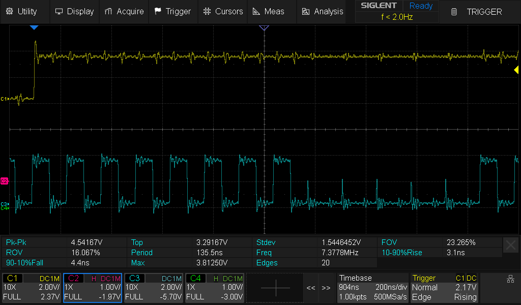
With this setup the glitch will occur when TIO4 goes high; you should get something like this:
Thanks - that’s giving me a glitch that I can see on the scope.
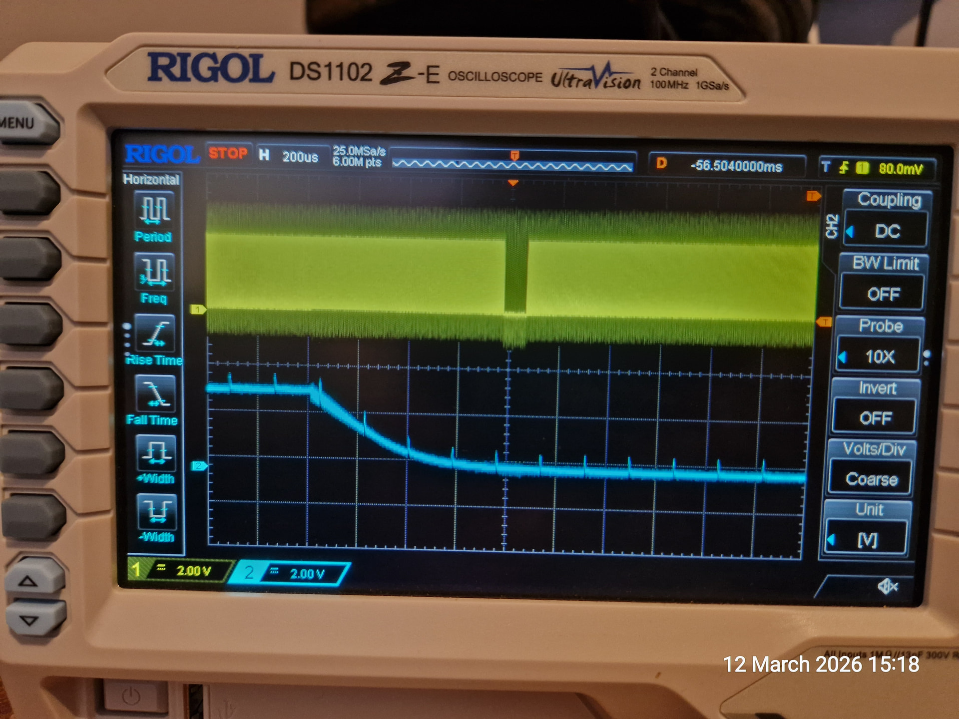
I seem to have an issue with larger ext_offsets (>180k ish) where the glitch is placed after the rising edge of the trigger (blue) not falling. This then “loops around” to the start.
Any ideas?
I may have misunderstood, but this looks like normal behaviour.
The key to understanding is that in this example configuration, the glitch will happen scope.glitch.ext_offset cycles after each trigger, BUT there is only a single ext_offset counter in the hardware. So if a second trigger event occurs when a first trigger’s ext_offset hasn’t been reached yet, then the second trigger isn’t seen and won’t result in glitches.
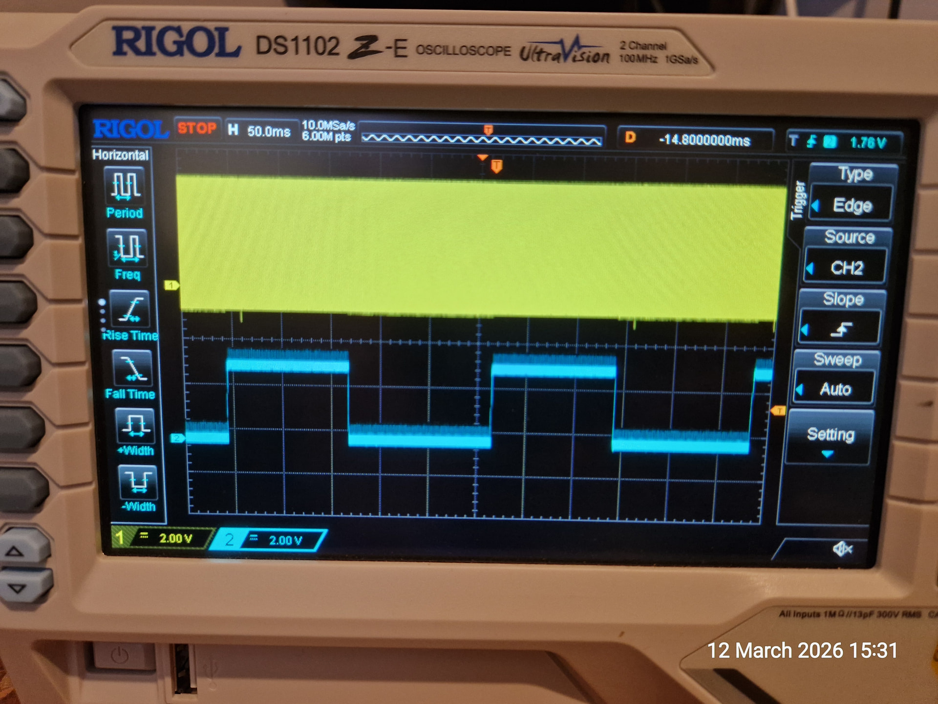
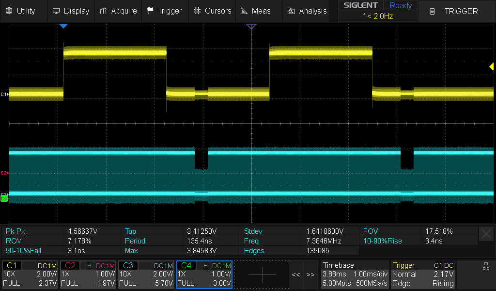
A simple illustration: in the first case, the second trigger doesn’t overlap the first trigger’s associated glitch, so both triggers generate a glitch. (yellow = trigger, blue = fast clock)
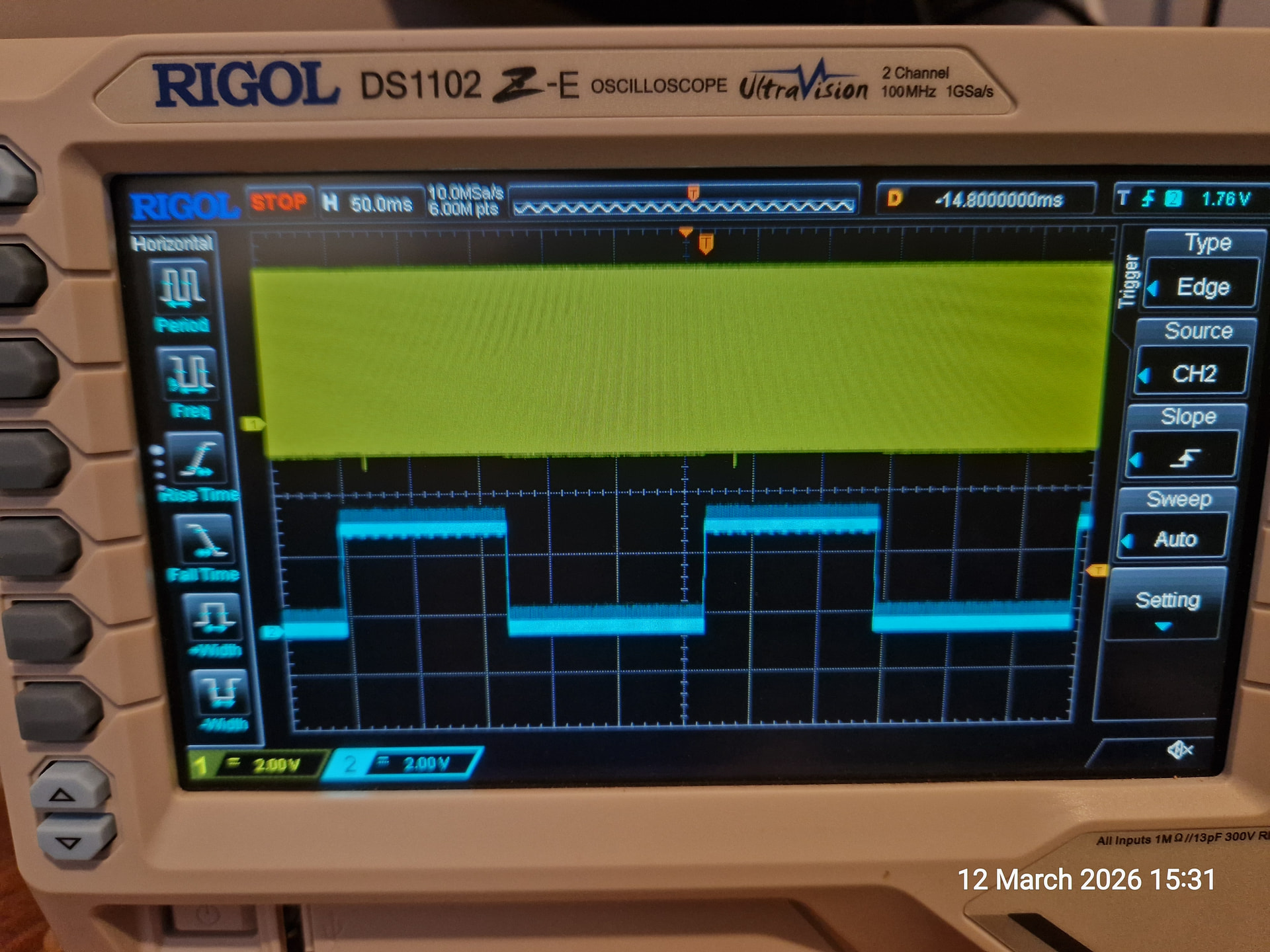
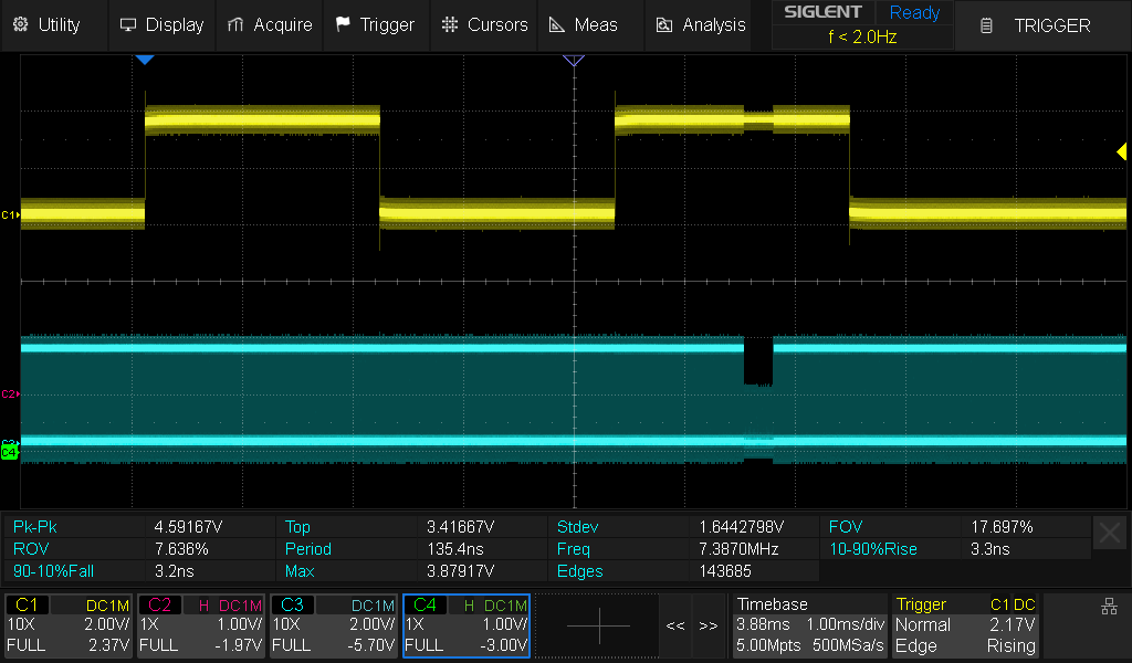
In the second case, I’ve increased scope.glitch.ext_offset to push out the glitch after the second trigger; because the second trigger happens before the first trigger’s glitch has gone out, it’s ignored.
1 Like
In case anyone is interested, I did a write up on what I was working on. However, I never did manage to get a useful glitch from the CW-Lite and had to resort to other means.
https://medium.com/@forums_2900/discret-14-reverse-engineering-a-lost-scrambling-system-3cb71917d7a7