Hello,
Can someboy explain to me why this is happening?
I wanted to compare the measurements of same function in different targets, so to avoid complications I choose the stm32f0 ripped off the nano
I choose the Lab 2_2b to start, so I began with the first cells of the notebook:
Husky was detected as usual
Also STM32F0 was detected and programmed without problems.
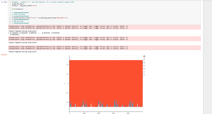
BUT when tried to capture a trace I only was able to get timeout while capturing as can be seen at the screenshot:
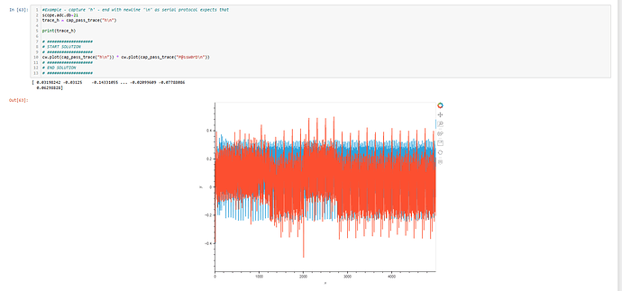
At first I though I connected something wrong or any other mistake, but after some testing I realized that the timeout error is gone if I unconnect the PDIC from boot0 after programming the STM32, with this cable disconnected the capture is done without error:
At this point I only know that with:
 PDIC connected to boot0 - STM32 can be programmed but the capture fail with timeout
 PDIC disconnected from boot0 - I can capture but can not program the stm32
To check if the problem was that the PDIC voltage was not returning to 0 after programming, I connected the oscilloscope to PDIC and looked first with the Boot0 pin disconnected… I saw the PD value rise for 4.5 seconds before The programming attempt failed due to a timeout, as expected since Boot0 was not connected at the time because I just wanted to see if the value was returning to 0 after being programmed, this was a success, so the next step was to check what was happening after programming that was causing the capture to time out, so I connected PDIC to boot0 with the oscilloscope connected, but this time the notebook went from programming to capture without giving any error behaving as it should from start to finish, so I have not been able to know what causes the timeout when PD is connected to Boot0 since the simple fact of measuring with the oscilloscope prevents the error from occurring.
When I was disconnecting the oscilloscope, the capture was still taking place, first I disconnected the gnd cable from the probe and at that same moment the capture started to fail again due to timeout behaving the same way as when the oscilloscope was not connected at all, having to disconnect boot0 so that the capture could continue
So this is what I observed:
 PDIC connected to boot0 - Can program but can not capture
 PDIC disconnected from boot0 - Can capture but can not program
 PDIC connected to boot0 with oscilloscope attached - Can program and also can capture
 PDIC connected to boot0 with oscilloscope attached (GND of probe not attached) - Can capture but can not program
I must admit I have no clue what is happening or what I’m doing wrong (Again!! yes!!) But if I had to bet I would say that when PD is connected to boot0 (without the scope attached), the stm32 receive some kind of interference, or whatever make it not to boot into normal operation mode, and when the scope is connected that interference is grounded by the scope’s probe… Could that explain why it boots into normal operation mode when PD is disconnected? Is this possible?

