I am trying to run a continuous glitching test, using the chip shouter. I am using the HW trigger around 30 per sec, voltage set at 500V, pw at 160nS. I see the temperature rose to about 45, and as high as 47C. Every 10 seconds I poll for temperature, and every minute I poll for faults. I left this run overnight.
Today, after about half and hour one or more of the temperatures goes to 0. Sometimes to -1. Eventually I get a fault latched overvoltage, and the red fault light comes on. I can shut off the light by sending the “s f n” command, but it comes back immediately. The only way that I can reset seems to be to power cycle.
The temperature never gets above 50C. We are using an aquarium pump to pump in air. What would you suggest as a limit?
I am right now getting -1C as a temperature. I pause for 60 seconds, restart the test. Still -1C. It seems like this is latched in, even though there are no faults.
I pull the power, and restart the test. It runs and read 43/41/38 as temperatures.
Also, when I send s p w 80, or s p w 160, the voltage out of the voltage monitoring port remains unchanged. Should the pulse width be increasing here?
[Sorry removed an in-between post to avoid confusion if you see the odd reply, as a few things weren’t quite correct].
Those fault conditions occur when the safety mechanism can’t perform a read from the temp sensor. It’s not a case of overheating, as that will still return a valid temperature. It returns -1 when it cannot successfully read the temp from the internal sensor. The temp reads will fail/be invalid during discharge event - the most often occurs due to rapid external or internal triggers normally.
If the -1 state gets latched, this normally means the read failed too many times in a row so the device “disabled” that temp sensor. The failsafe you are seeing is that to avoid the device overheating/being damaged due to a missing temp sensor reading.
You can call the “triggersafe” command to see if that forces a correct read. Basically the problem is attempting to read the temp sensor during a discharge event may cause a latched error. The “triggersafe” command helps avoid this (see page 48/49 of manual in ChipSHOUTER User Manual which briefly mentions this).
If you get the error - does it clear the error when you perform a soft reset (with ‘reset’ command)? If the error remains latched, it could be a problem on the temp sensor itself if it requires a hardware power cycle.
Normally you can get around the problem by adjusting the pulse width/voltage/etc. We’ve found various corner cases that cause odd behavior such as this.
Finally - there is a setting called absent_temp you can try. This setting specifies how long the temp sensor is invalid for before it flags an error. If the sensor is indeed latching to -1 that might not be enough, but increasing that value might give you time to detect it via the API and recover gracefully (assuming the soft reset works OK).
But as a first step I’d see if calling triggersafe in-between glitches works. Check the value of absent_temp and increase that too.
That is very useful. Also, for some reason, when I send “r” it doesn’t understand. I need to send “reset” for the reset to work.
I am still having a problem with the pulse width. When I send “s p w 80”, or “s p w 160”, or “s p w 640”, the voltage waveform as measured from the voltage monitoring port by an OSCOPE remains unchanged. Should the pulse width be increasing here? I also am measuring the field along side the fault injection antenna, and it is also unchanged.
Ah - might need to update that! Normally the ‘reset’ isn’t a usual thing you want, so we might have avoided shortening it (despite if written in manual).
On the pulse width - two things:
The pulse width is limited by the probe itself. See Figure 2+3 of user manual for an example, it will vary slightly with actual devices. But you can see at higher voltages the pulse widths get limited due to the field saturation (the driver is attempting to push out the width, but it has limits).
If you are using the external hardware trigger (the SMB input), the pulse width isn’t used. Instead the hardware follows the actual hardware input. The pulse width setting is used only when commanding with the pulse command, or if using the pulse pin on the RJ12 connector.
As another note too - if you need to get better resolution on the pulse width, you can use the ‘pattern trigger’ mode. This mode has higher resolution than the base simple trigger (i.e., setting a pattern of 0110000 vs 01110000 vs 01111000 etc).
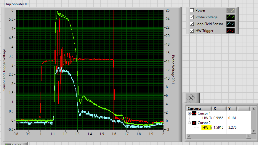
Also, here is a scope track of the input (from a Teensy CMOS 3.3 volt trigger. The trigger is set to about 0.5 uS long. Looks like the voltage monitor shoots up to about 500 volts, and then after 0.1 uS falls down to about 80 V. Is this expected behavior? The same thing happens as I increase the voltage. A quick spike, and collapse after about 150 nS.
I don’t think the temp fault is actually a temp fault. Attached is a communication log for about 40 minutes of my test. I took your recommendation and sent triggersafe before each trigger. I am using the hardware trigger. Every 5 seconds I poll for faults, and then I poll for temperatures. The temps are holding steady at around 43C. Randomly I am getting “#Error: Command not Found”. About line 49154, something strange starts to happen. I need to try the “g ts” commands. And at 31.634 seconds (line 49176, triggersafe goes to 0. It goes into fault mode, I reset and it recovers. Also note on line 49187 after the reset, it responds with what looks like a bunch of buffered responses. (race condition?). I would like to trigger faster. LMK recommendations to avoid restarts, and to trigger faster without these random resets.CW_Log1.zip (112.9 KB)
I am not seeing my chip reset, even with the largest pulse, with the largest coil touching the chip.
What are the impedance specs for the probe tips, in case I want to make one with a larger loop?