Using ChipWhisperer to trigger ChipShouter

Hi all,
I am trying to use the chipWhisperer as a trigger for the chipShouter.
Using the Python API to configure the chipShouter and then manually arming and pulsing, I get different kind of waveforms, that change their amplitude and duration as expected.
But when I try to use the same settings through external trigger (chipWhisperer scope.glitch sma port using lowpower glitch configuration to chipShouter’s smb port) I always get the same waveform measuring through oscilloscope.

As suggested in cs manual i have set:

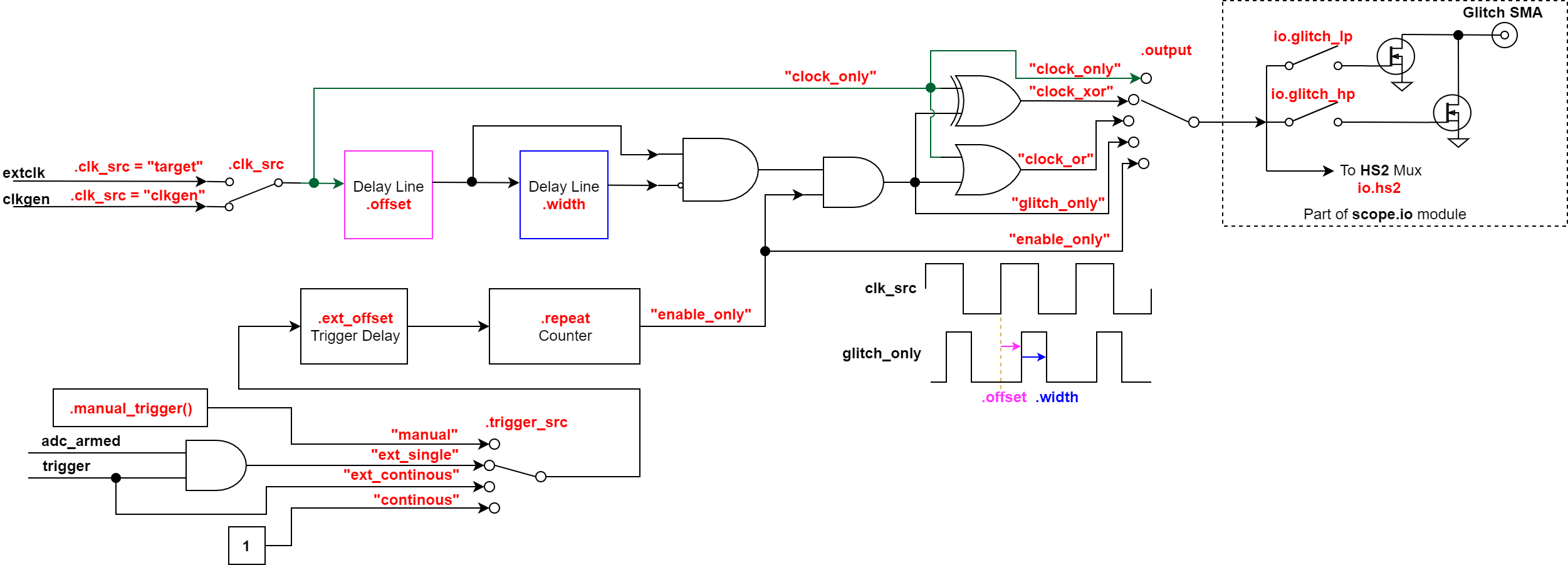
scope.glitch.output = "enable_only"
scope.io.glitch_lp = True

cs.hwtrig_term = False
cs.hwtrig_mode = False

SCOPE state

cwlite Device
sn         = 4420312046304a383030342035303038
fw_version = 
    major = 0
    minor = 30
    debug = 0
gain = 
    mode = high
    gain = 30
    db   = 24.8359375
adc = 
    state          = False
    basic_mode     = rising_edge
    timeout        = 2
    offset         = 0
    presamples     = 0
    samples        = 5000
    decimate       = 1
    trig_count     = 3271224352
    fifo_fill_mode = normal
clock = 
    adc_src       = clkgen_x1
    adc_phase     = 0
    adc_freq      = 7384609
    adc_rate      = 7384609.0
    adc_locked    = True
    freq_ctr      = 0
    freq_ctr_src  = extclk
    clkgen_src    = system
    extclk_freq   = 10000000
    clkgen_mul    = 2
    clkgen_div    = 26
    clkgen_freq   = 7384615.384615385
    clkgen_locked = True
trigger = 
    triggers = tio4
    module   = basic
io = 
    tio1         = serial_rx
    tio2         = serial_tx
    tio3         = high_z
    tio4         = high_z
    pdid         = high_z
    pdic         = high_z
    nrst         = high_z
    glitch_hp    = False
    glitch_lp    = True
    extclk_src   = hs1
    hs2          = clkgen
    target_pwr   = True
    tio_states   = (0, 1, 0, 0)
    cdc_settings = array('B', [0, 0])
glitch = 
    clk_src     = clkgen
    width       = 10.15625
    width_fine  = 0
    offset      = 10.15625
    offset_fine = 0
    trigger_src = ext_single
    arm_timing  = after_scope
    ext_offset  = 0
    repeat      = 8190
    output      = enable_only

CHIPSHOUTER state

api_version         = 0.0.0
armed               = True
voltage = 
    set      = 300
    measured = 296
pulse = 
    width        = 190
    repeat       = 1
    deadtime     = 10
    actual width = 240
state               = armed
trigger_safe        = True
faults_current      = []
faults_latched      = ['fault_trigger_glitch']
temperature_mosfet  = 35
temperature_diode   = 31
temperature_xformer = 42
arm_timeout         = 2
hwtrig_term         = False
hwtrig_mode         = False
emode               = False
mute                = True
absent_temp         = 1
pat_enable          = False
pat_wave            = 0110000
reset_config        = 0
reset               = False
board_id            = HVFO3B:1.8.7

boot_enable         = 0

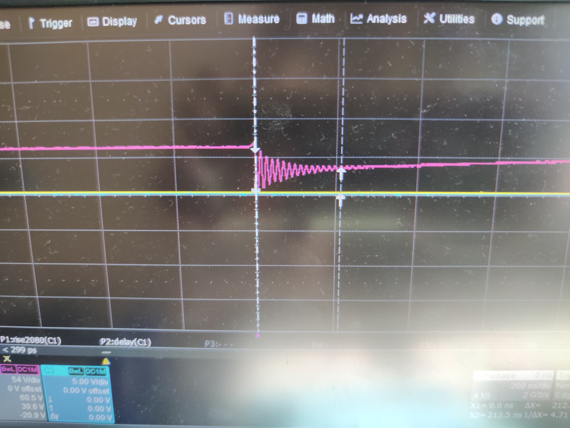
Top left corner : 180ns width 300v using cw trigger
Top right corner: 180ns width 300v manual
Bottom left corner: 360ns width 300v using cw trigger
Bottom right corner: 360ns width 300v manual

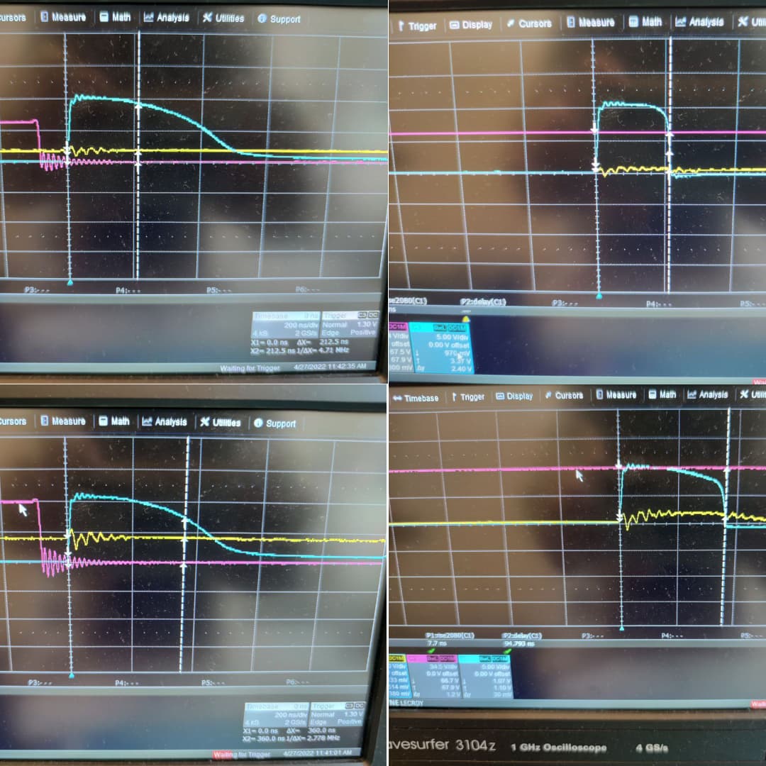
As you can see the pulse width looks exactly the same for the two different settings, how can i solve the problem? Thanks in advance

edit:
I don’t know if it can be helpful but another difference I have noticed is that the beep sound of the chipshouter triggers only when used manually or through python, and is not hearable when triggered via chipwhisperer

The reason you see this is because the SMB trigger is tied directly to the glitch driver instead of going through the microcontroller like the button/Python pulses. You should be able to get different waveforms by varying the length of the trigger instead of via ChipSHOUTER settings.

Alex

Thank you so much for your answer, may I ask further how to vary the trigger length using the chip whisperer? The only parameter that seems making it change (and i think its confirmed by this image on cw api doc https://chipwhisperer.readthedocs.io/en/latest/_images/cwlitepro_glitch.png) is scope.glitch.repeat , but using low values such as 1 or 2 is not even sufficient to be perceived by the chipshouter as a real trigger signal.

There i am using repeat = 3 and it doesn’t trigger cs.

edit: is it okay that the chipShouter active low trigger to be pulled down is 70V high?

Are you sure it’s 70V? A voltage that high will immediately destroy the CW glitch MOSFET and probably destroy other things on the board. It’s far more likely that your oscilloscope probe doesn’t match the ratio you have set in your scope.

edit: the signal is 3.3V, you were right, i wasnt aware of the probe ratio, thanks

But i still haven’t figure out how to effectively make an active low trigger signal that lasts 5ns.
I thought that using scope.glitch.repeat = 1 i would had a single cw clock cycle of glitch port grounded, but the transition is as slow as you can see in my last message (too slow).
Is my goal feasible with cw only? I have seen a few papers using this setup effectively, eg https://www.usenix.org/conference/woot19/presentation/oflynn

Yeah you should be able to use the glitch port. I haven’t experimented with very short widths, but I’d say 5ns is just too short of a width to insert with this setup. You might have more luck if you use the HS2 output from the advance breakout board (CW506 Advanced Breakout Board - NewAE Hardware Product Documentation) and the 50-ohm input mode.

Thank you for your help! I have managed to pulse at nanoseconds’ granularity using an fpga together with the advanced breakout board.