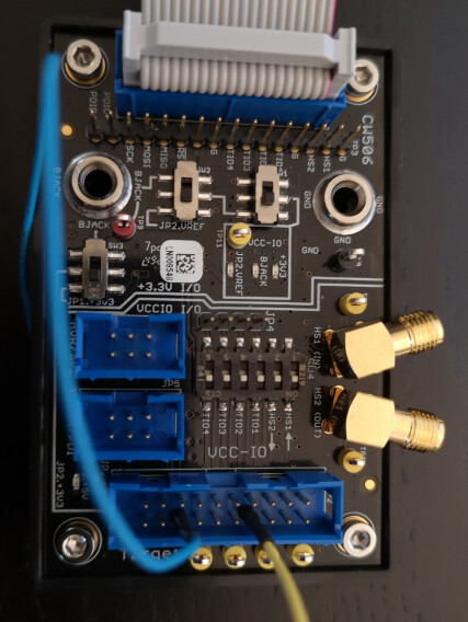
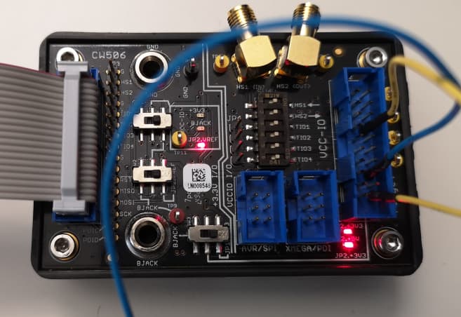
The yellow cable is set to PIN8 as VREF, it will contain a 5V signal. The blue cable is the trigger signal, which is also 5V on PIN16 for the TIO4 (I trigger on that PIN on CW). Is it actually possible to connect the yellow cable to the 20th pin, which is constant 5V?
I set up the SW1 to JP2.VREF, from my understanding it should then get the voltage from VREF and “translate” the 5V signal from the JP2 PINS to the CWPRO JP1 as 3.3V signals. Is that setup correct?
If I use the BJACK to provide the 5V voltage, do I also have to use the GND to ground it?
should I connect any of the JP2 GND pins to a GND pin on my target device?
I connected the yellow pin to the 20th JP2 pin
Im wondering how much current can a trigger signal have? Lets say I dont use the CW506, which resistors should I chose or how many Ampere do I need/cant exceed in order to not break the device, when I connect the wire directly into tio4 of CWPRO? In other words, how much ampere should my signal have after applying a voltage reduction using resistors?
is the actual setting correct? the VREF is connected to 20th pin which is from the power source, wont it cause any trouble?