Hi,
I would like to Vcc glitch a target connected through the CW308. I looked at the schematics, and at Alex Dewar’s answer about making a fully custom target here (Trigger not found in ADC data. No data reported!), and the requirements to use it with chipwhisperer.
I tried to connect everything according to the provided info, but I think I missed something.
The setup is the following:
CW Lite connected through 20-pin J1 to CW308.
J4 set to cw as Vref
J3 to H2S/OUT
J16 not set at all
LDO-s set to CW/J1
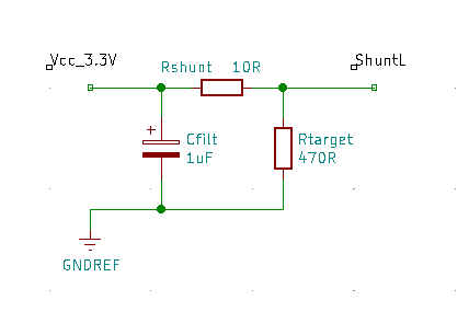
The target gets power from the 3.3V output of the J11 side, through a 4Ohm, approximately 6W power rated resistor(shunt). The high side of the shunt is connected to ground through a 1microFarad capacitor (I left out the 0,1uF capacitor, as can be seen on some NewAE provided targets). The target side of the shunt resistor is connected to the CW308 SMA, which should get the glitch from the glitch output of the CW Lite, since I connected them. My target is a cortex-M4 ARM. I did not connect the target’s clock, but generated one with the (almost) same frequency.
The cw scope settings are the following:
clk_src = clkgen
width = 10.15625
width_fine = 0
offset = -19.921875
offset_fine = 0
trigger_src = ext_single
arm_timing = after_scope
ext_offset = 0
repeat = 3
output = glitch_only
cwlite Device
gain =
mode = low
gain = 0
db = 5.5
adc =
state = True
basic_mode = rising_edge
timeout = 2
offset = 0
presamples = 0
samples = 10000
decimate = 1
trig_count = 324538461
clock =
adc_src = clkgen_x1
adc_phase = 0
adc_freq = 96000000
adc_rate = 96000000.0
adc_locked = True
freq_ctr = 0
freq_ctr_src = clkgen
clkgen_src = system
extclk_freq = 10000000
clkgen_mul = 2
clkgen_div = 3
clkgen_freq = 64000000.0
clkgen_locked = True
trigger =
triggers = tio4
module = basic
io =
tio1 = high_z
tio2 = high_z
tio3 = high_z
tio4 = high_z
pdid = high_z
pdic = high_z
nrst = high_z
glitch_hp = True
glitch_lp = False
extclk_src = hs1
hs2 = None
target_pwr = True
glitch =
clk_src = clkgen
width = 10.15625
width_fine = 0
offset = -19.921875
offset_fine = 0
trigger_src = ext_single
arm_timing = after_scope
ext_offset = 0
repeat = 3
output = glitch_only
However, when I look at the SHUNTL output with an oscilloscope, I cannot find any disturbance apart from minimal noise in the power output of the chipwhisperer. The blue “trigger armed” LED is lit up. Of course I can get the disturbance shown when I disconnect the power by hand, ruling out measurement error on the oscilloscope side.
The glitching is done with these lines(inside multiple loops):
glitch_on(scope)
scope.arm()

ret = scope.capture()
if ret:
    print('Timeout happened during acquisition')

glitch_off(scope)
Do you have any idea, why I cannot see a glitch, neither timeout error, with continous arming present(not even with glitch_hp)?
Best regards,
Norbert