I’m trying to replicate some glitching on ESP32 boards, I saw also the schematics from the CW308T-ESP32 but I would like some help to clarify some doubt.
ESP32 has 2 different PIN, VCC_RTC and VCC_CPU. From previous research we know that the chip has some “protection” on VCC_RTC which identify and reboot the chip in case of power loss/glitch. So I need to provide a stable 3.3v on VCC_RTC and a “glitchable” 3.3v on VCC_CPU.
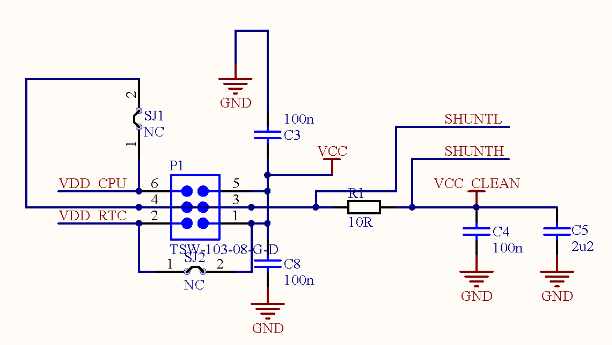
Based on the CW308T-ESP32 schematics I suppose that SJ1 and SJ2 has been created to separate and provide 2 different 3.3v lines and bypass this problem. In my board I cutted the PCB to have the same situation with two different lines.
Currently I’m working on an Husky and my doubt is how to provide two separate 3.3v to the ESP32. On the 20pin connector I got on pin 3 the controllable 3.3v (max 200ma) and on pin 18 the 3.3v line.
If I use these two pin and glitch on the VCC_CPU connected to the PIN3 I will in some way interract and modify also on the pin18 3.3v line? From my understanding no, but I would like a confirmation.
The two 3.3V lines from the CW-Husky are indeed connected together internally.
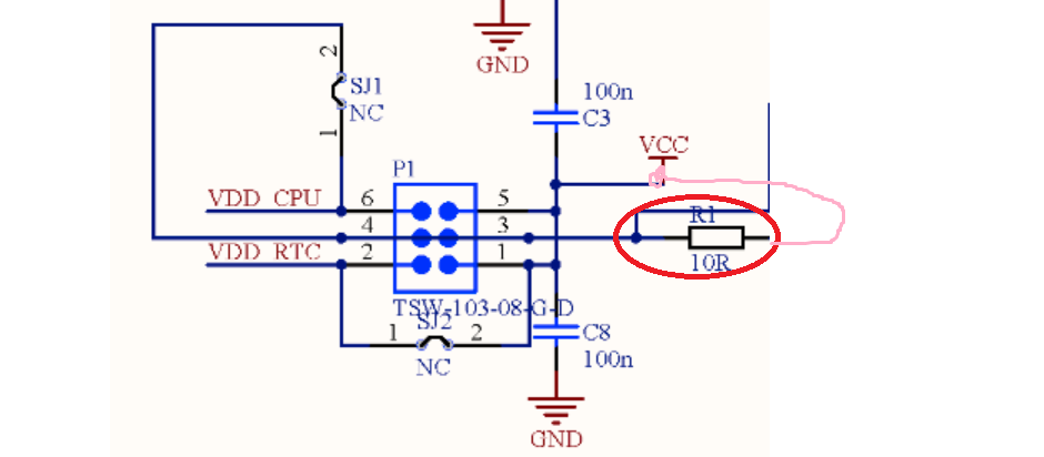
But what we normally do is run the VCC that you will glitch through a small shunt resistor (1-10 ohms). The jumpers on the ESP32 board you reference are designed to allow that (but if you wanted to do something on VCC_RTC for example could also do that). In your case, basically I think what you want is like this, with the line in pink added:
The VCC_CLEAN on the ESP32 is the result of filtering the VCC, so if you don’t care as much about the filtered output, you could just use the VCC line for both. Adding the resistor R1 means the glitch will be filtered from the VDD_RTC line. You might need to experiment with R1 a bit.
Ah sorry - didn’t specify, glitch would be on VDD_CPU, on the “low” side of the resistor. You might need to separate the incoming power a little or add some caps on the “high” side to ensure there is a smaller ripple there still.
Pulling the two 3.3V rails from different CW-Husky pins will provide some separation due to the e.g. inductance of the wires & traces. But I’d still add a little extra with a resistor