Hi everyone,
I met a problem while configuring my third party board before launching some glitch.
In fact, from the starter Kit Level 1 provided by NewAE Technology, I still use the following elements:
-CW-Lite board for voltage fault glitching ;
-CW308 UFO board mainly to use the 1.2V to supply the VCore of my target (obviously I removed the decoupling capacitors).
I want to configure my third party board in order to test a specific code with VFI. The problem is the 1.2V generated by the CW308 UFO board because it isn’t very stable and it prevents me to configure dynamically my target → With a scope capture, I can see some oscillations.
Is there a configuration way to adjust this voltage or filter oscillations with the CW308 UFO board ?
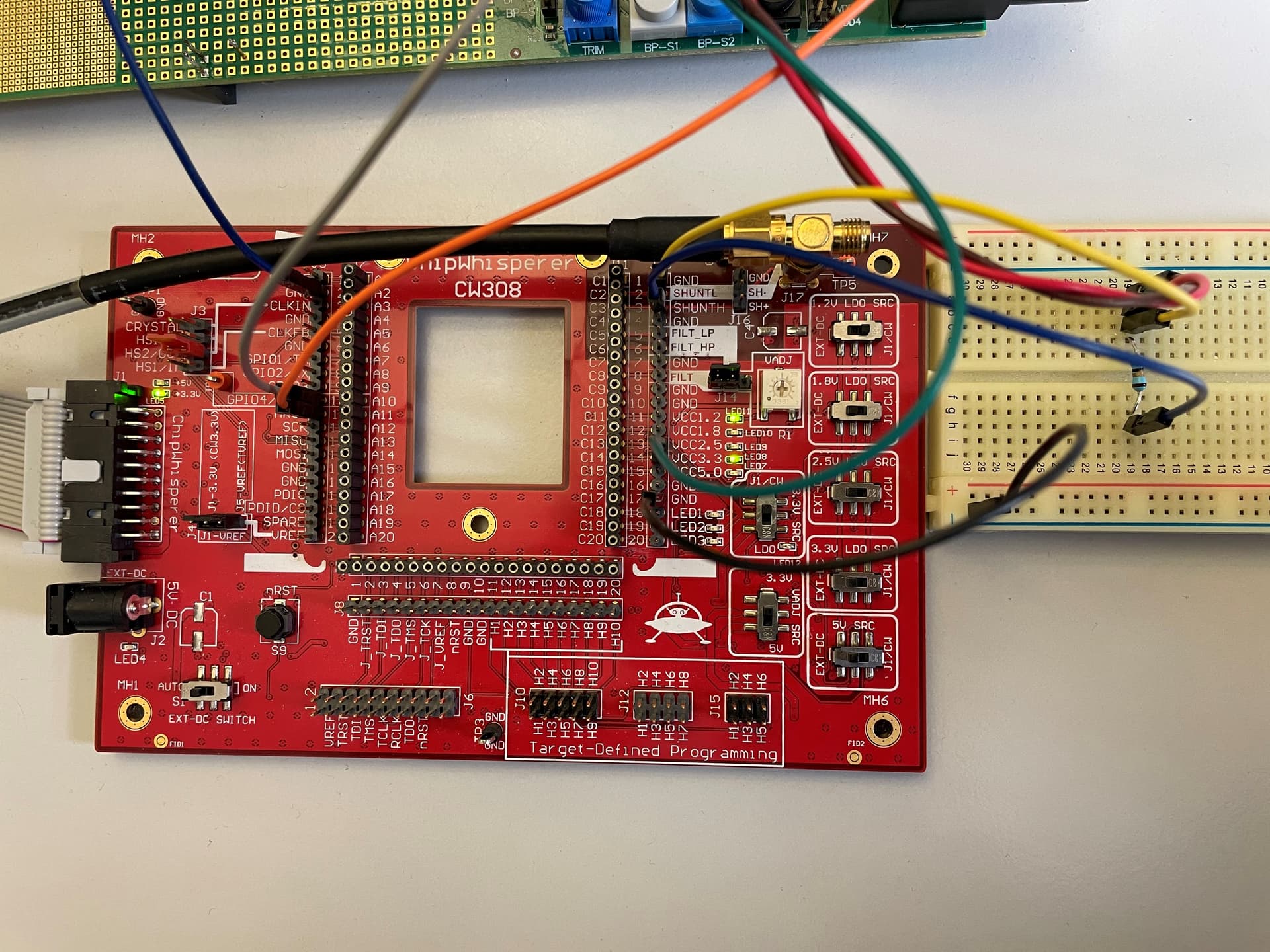
(At this point, I put the J4 jumper for getting 3,3V from CW, then 1,2V LD0 SRC on J1/CW position, then VADJ on 3,3V, then J1/CW on 3,3V src)
Below a picture of my CW308 Full Configuration
Hope it can help !
Thanks by advance to your return !
You need to switch your 1.2V supply to the actual VCC1.2V pin. The SHUNT/FILT pins are routed on the target board, so they’re not hooked up to any supply on the CW308 itself
Hi Alex,
You need to switch your 1.2V supply to the actual VCC1.2V pin. The SHUNT/FILT pins are routed on the target board, so they’re not hooked up to any supply on the CW308 itself
In my case (with my third party target board) I applied the same connections as those done with STM32F Target Board for ChipWhisperer CW308 UFO Board … except for FILT_LP/_HP & FILTIN & VCC1.2V.
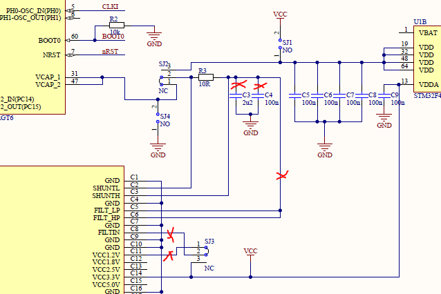
You can see my resume schematic below
In that case, I was able to glitch a very basic code (counter increment with double loop).
With this setup, the problem is the following as I said in my last message: I can’t dynamically configure my third party board because of instability on the VCore Supply (I checked with a scope and the voltage oscillates between 1.2V and 2.0V).
So, my first question is: In this configuration, where does this supply voltage comes from ? (SHUNTH is connected to which supply voltage ?)
Then, I made some tests by switching the connections from SHUNTH (connected to the high side of my R3 resistor) to first VCC 1.2V, then VCC 1.8V. I well observe the glitch waveform but it’s impossible for me to glitch my code as previously with SHUNTH connected to the high side of R3.
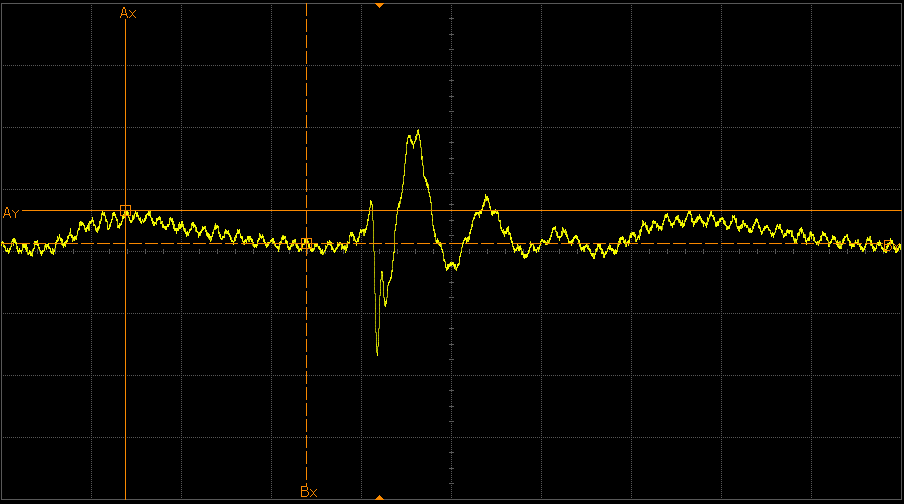
First scope capture with VCC 1.2V
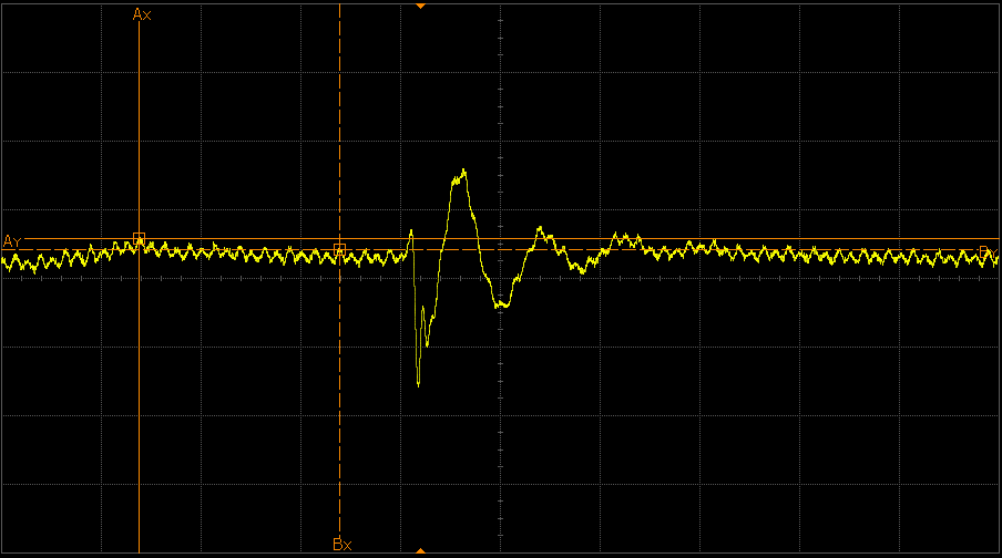
Second scope capture with VCC 1.8V
As you can see, the VCC 1.8V oscillates less than the VCC 1.2V. And what I don’t understand is that I didn’t get proper 1.8V with VCC 1.8 pin but 1.5V  - Do it can come from bad configuration from my CW308 UFO board ?
Thanks to your return !
If those red X’s are open circuit, SHUNTH won’t be connected to anything. In the “A” configuration (F2, F4), SJ3 connects VCC1.2V and FILTIN, the latter of which is connected to FILTHP/FILTLP. In the “B” configuration (F0, F1, F3), SJ3 connects VCC3.3V and FILTIN instead.
C3 and C4 are also important here, as we want the high side of the shunt resistor to be as stable as possible.