Hi everyone,
Because I want to attack my own ECC algorithm, I need to modify cw305_ecc_p256_pmul_top.v file and generate new bit flie for my case. First I try to use vivado to generate same bit flie in CW305_ECC but met some problems. I want to ask about how to generate bit flie in CW305_ECC. Which file should I add in vivado project?
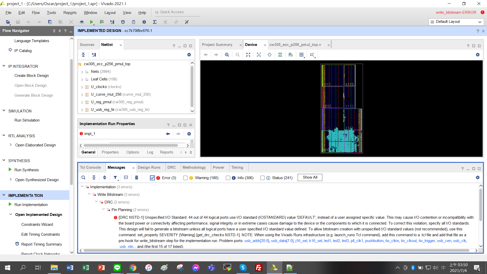
Looks like you have an issue with your constraints file.
Have a look at our reference ECC project:
1 Like
Hi,after I see the .xpr file and open that project, I still find some error
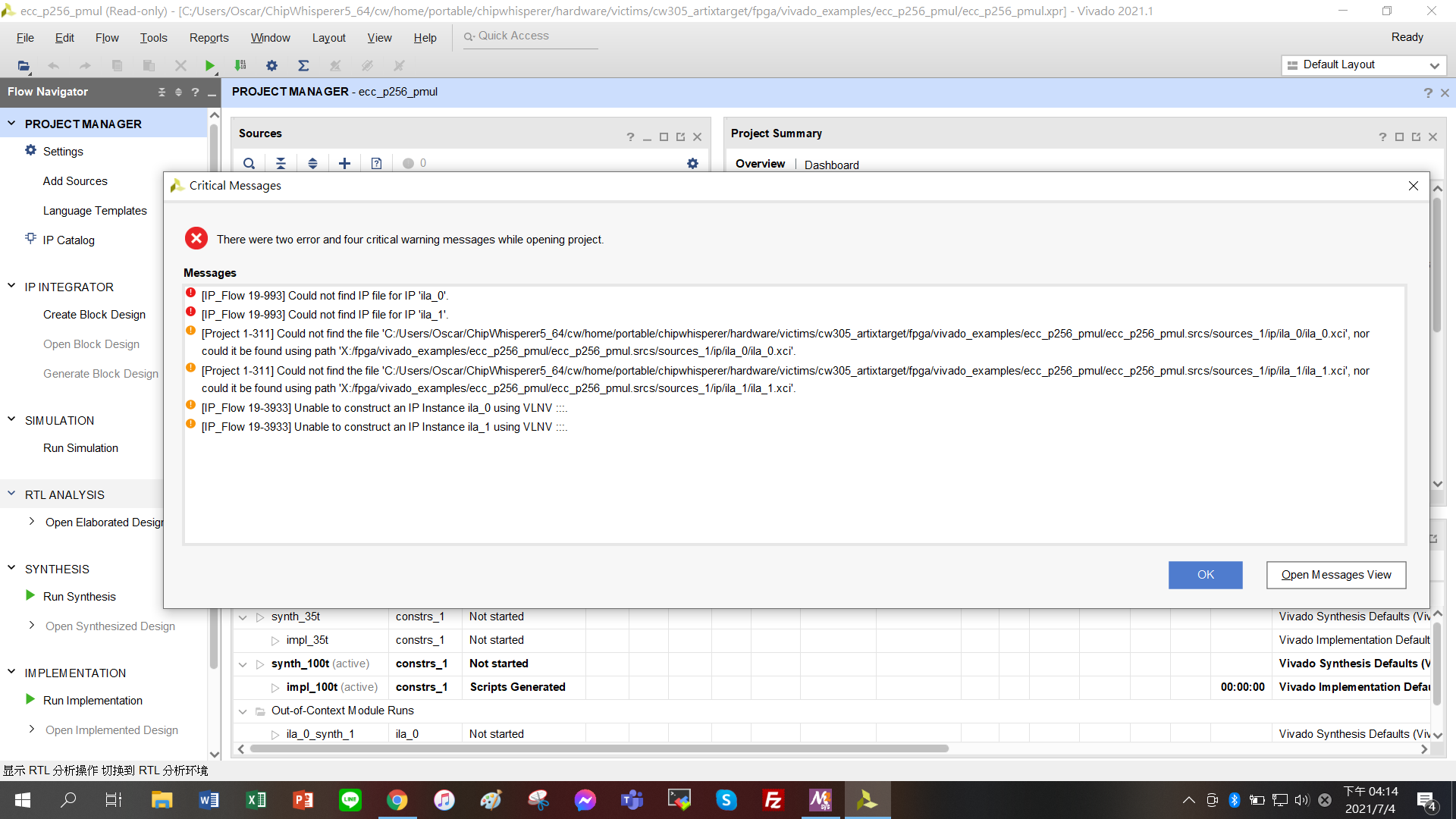
where could I fine the IP ila_0 and ila_1?
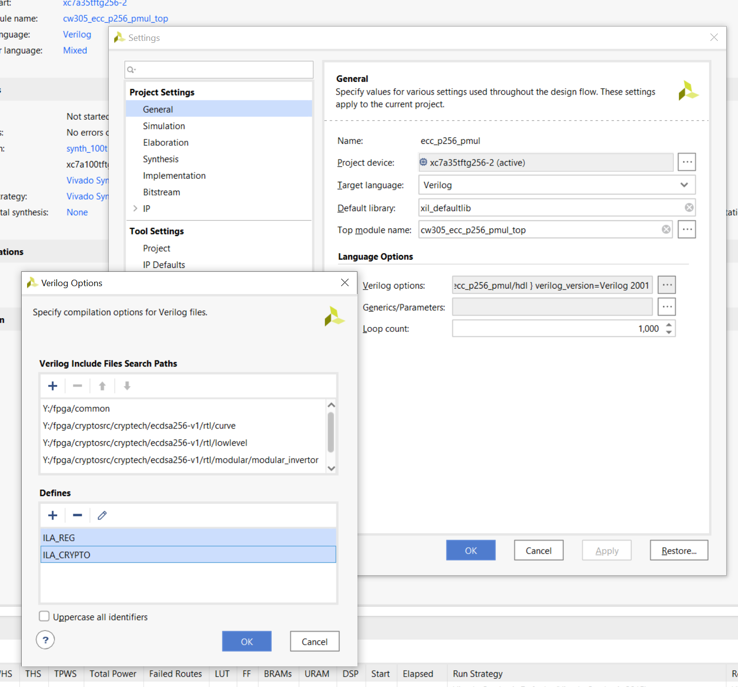
You can either remove the ILAs: under “Settings”, “General”, “Verilog options”, remove the ILA_REG and ILA_CRYPTO defines:
Or if you prefer to keep them in, I added the ILAs on this commit:
Jean-Pierre
1 Like
Thank you.It helps me a lot.
And I have another question.When I successfully generated my bitfile(my own ECC algorithm) from vivado, and then I uploaded to replace the bitflie here with same name.
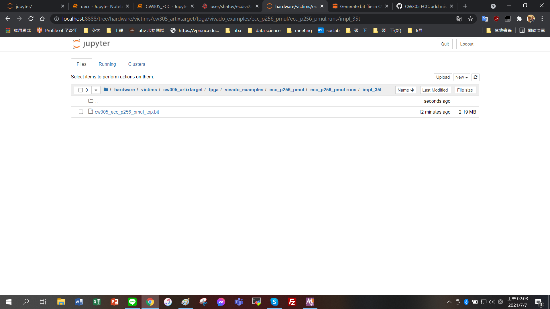
Is here a correct place I replaced the bitfile?
Because the result seems the same compared with the original CW305_ECC demo.
No, that is not where the bitstream is taken from.
The easiest way to program your bitstream using ChipWhisperer is this:
target = cw.target(scope, cw.targets.CW305_ECC, bs=<your bitstream>, force=True)
Jean-Pierre
1 Like
Hi, thank you for your response, but I still confuse about where should I put my bitstream file.
which file should it take in the demo?And where?
And should I keep fpga_id=‘35t’?
The bitstream can be anywhere on your filesystem, for example
target = cw.target(scope, cw.targets.CW305_ECC, bs='C:\Users\me\bitstream.bit', force=True)
The fpga_id argument isn’t needed since you’re specifying the bitstream explicitly.
In our demos, the bitstreams come from software/chipwhisperer/hardware/firmware/cw305.py
Jean-Pierre
1 Like
Thank you. I successfully input my bitstream.
But I still get some problem which makes me confused.
Here is what I do:
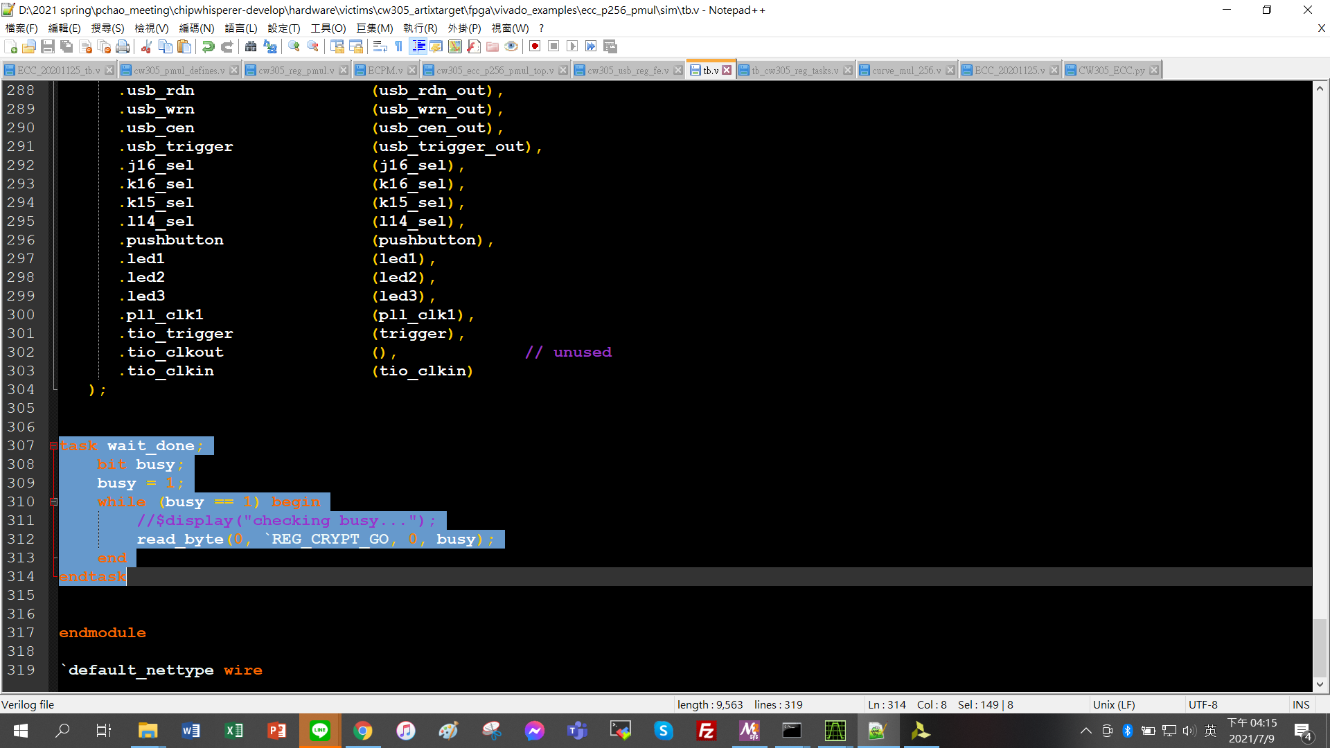
I replace the original curve_mul_256.v with my own ecc algorithm (ECPM.v), also modify cw305_ecc_p256_pmul_top.v and cw305_reg_pmul.v file and do the simulation.
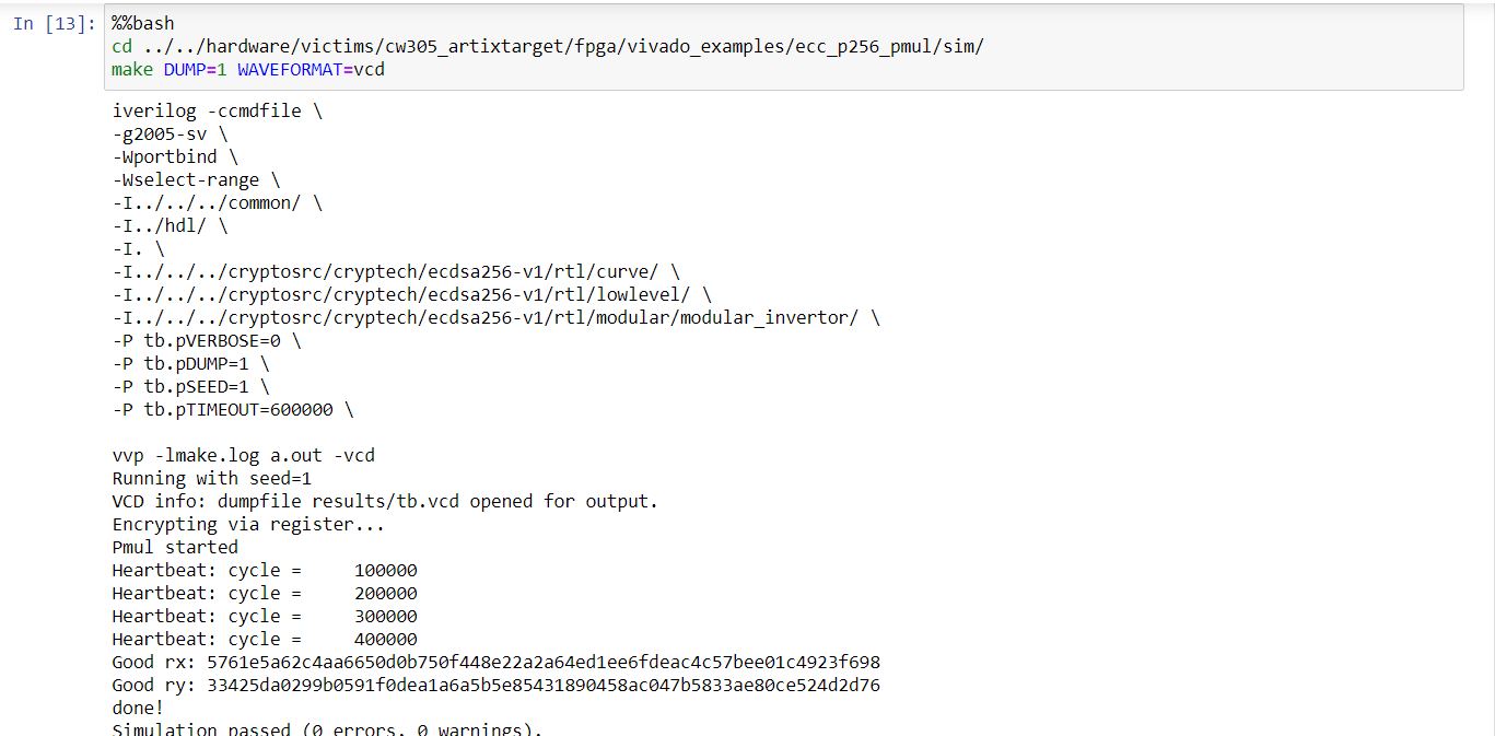
And I use gtkwave to open the .vcd file and the signal & result look correct.
But when I use vivado to generate bitstream file and put it to the CW305_ECC for run.
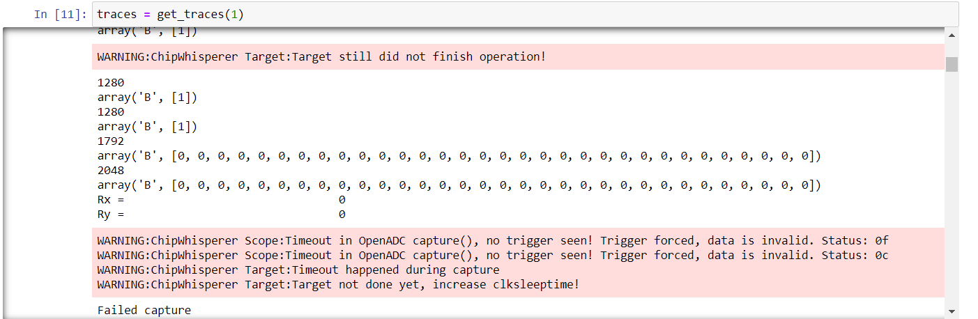
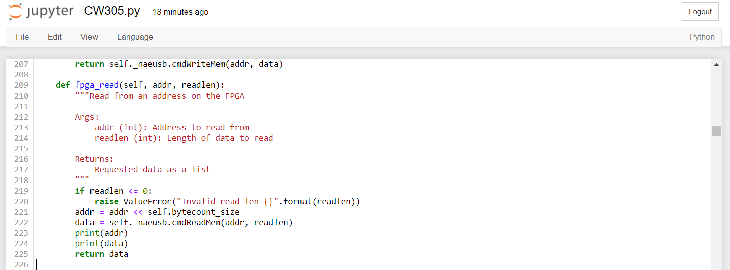
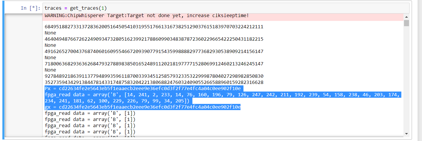
the number(1280, 1792, 2048) is the variable addr and the array is variable data in fpga_read function
which I print from
compare the result of original bitstream file
I think I get some promblems in these two lines
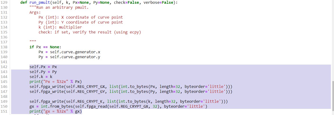
Rx = int.from_bytes(self.fpga_read(self.REG_CRYPT_RX, 32), byteorder=‘little’)
Ry = int.from_bytes(self.fpga_read(self.REG_CRYPT_RY, 32), byteorder=‘little’)
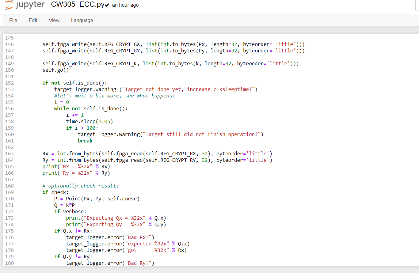
Can I get some hints about how to debug if I can’t successfully get the data from fpga?
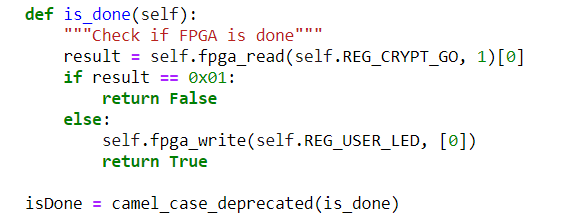
The “Target not done yet, increase clksleeptime” warning gives you a hint!
Maybe you need to increase CW305_ECC._clksleeptime (is your implementation slower than ours?).
Are you updating the REG_CRYPT_GO register when the operation is done? (you can see that this is what CW305.is_done() checks for before the above warning is reached).
It’s great that you have a working simulation; now work your way through what CW305_ECC.py does to run a capture to find what needs to be fixed.
Jean-Pierre
Hi, thank you for your response.
But for this question “Are you updating the REG_CRYPT_GO register when the operation is done?”
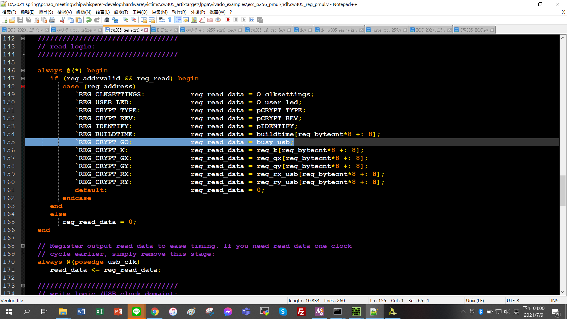
How could I check the REG_CRYPT_GO register from the RTL code because the result from CW305.is_done() seems not don’t yet obviously, I think the update algorithm in rtl code is in the cw305_reg_pmul.v
I also check the simulation
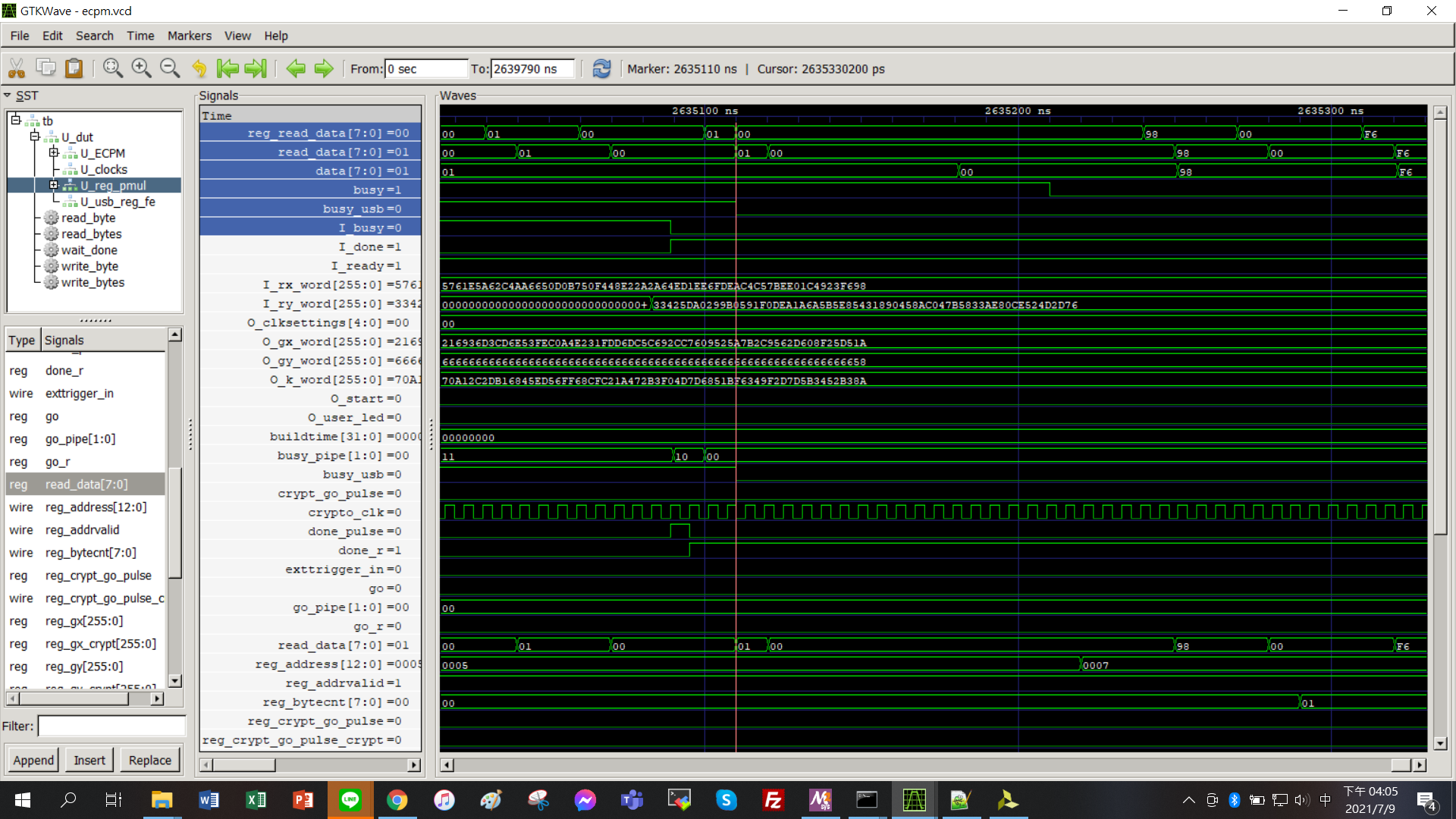
the signal(busy_usb) will be down when the operation is done. and the reg_read_data will be 0, so the signal(busy) in the tb.v will go to 0.
I can’t see where is wrong actually. Is my work correct?
I don’t result = self.fpga_read(self.REG_CRYPT_GO, 1)[0] will read what signal corresponds to the hdl code?(is not corresponds to the busy signal from the 'REG_CRYPT_GO in wait_done task in the tb.v?
Sorry for my noob question.
Can you check that you can reliably read and write registers from Python? E.g. write some random value to REG_CRYPT_K and verify that the same value is read back?
1 Like
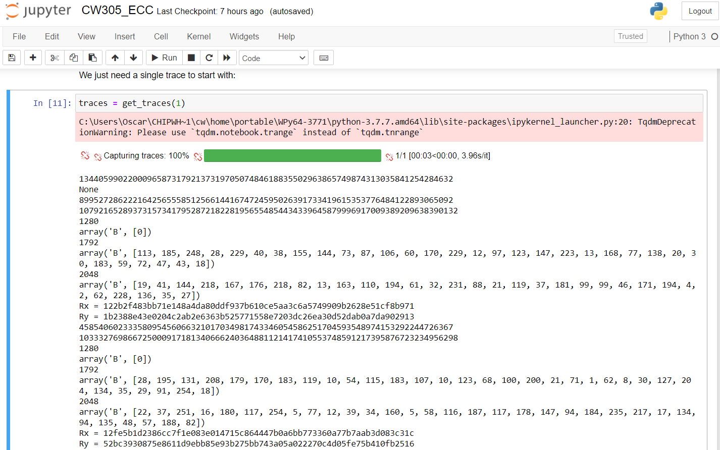
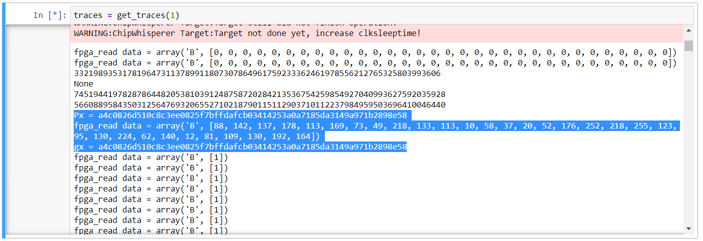
Yes, I check that the same value will be read back.
In CW305_ECC.py, I write
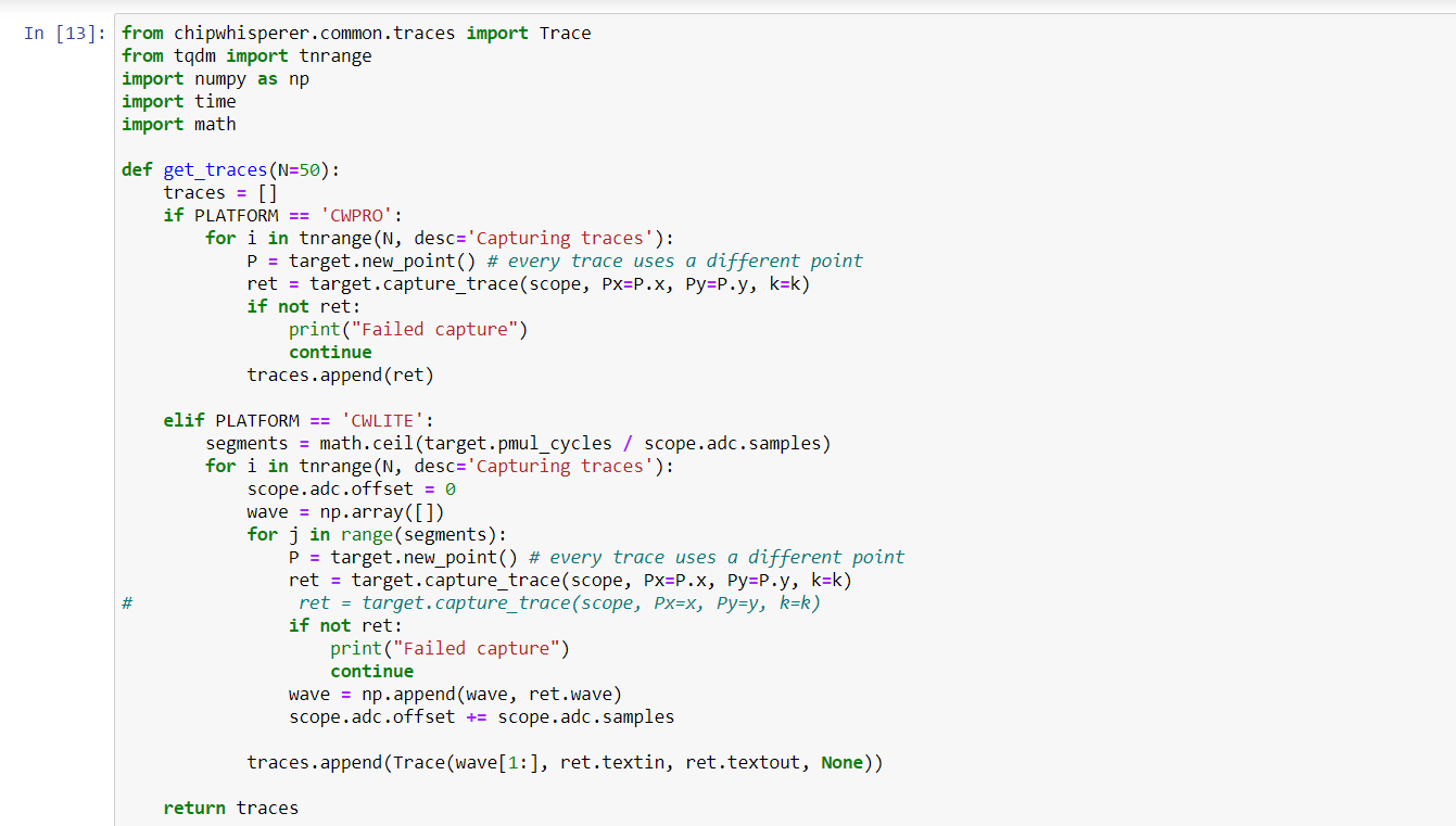
and then run the line ( traces = get_traces(1) )
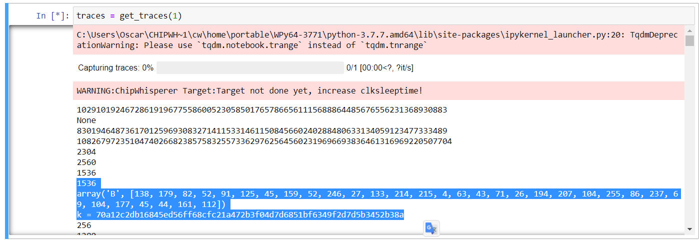
the value k is is read back with the same value I give
At this point if it were me, I would add ILAs to probe internal FPGA signals to figure out what’s going on. Start with the “go” and “done” signals and keep going from there.
Random thought: if you use X’s (unknowns) in your Verilog, it’s possible to have a mismatch between simulation and FPGA. X’s don’t exist on the FPGA, so the synthesis tool has to pick a 1 or a 0, and this may cause the design to behave differently from what you see in simulation.
Jean-Pierre
1 Like
Hi, just want to make sure, so I need to add ILA into cw305_reg_pmul.v to get the signal?(like ILAs in cw305_reg_pmul.v of demo)
And how could I see the probe of the ILAs signal? Still in the gtkwave simulation?
Thx for your help
Oscar
ILAs allow you to observe your design’s internal signals on the real target FPGA, not the simulated one. You can instantiate ILAs wherever you wish. Our example is just that. Your design is different from ours so you may wish to probe different signals.
You will find all you need to know about ILAs here: https://www.xilinx.com/products/intellectual-property/ila.html
There is a bit of a learning curve to using ILAs, but they are an essential tool for FPGA development and definitely worth learning. It’s like the software developer’s debugger.
Alternatively, you can route internal signals to the CW305 GPIO header and use an actual logic analyzer or oscilloscope to probe them.
Jean-Pierre
1 Like
Hi, just want to make sure if my thought is right.
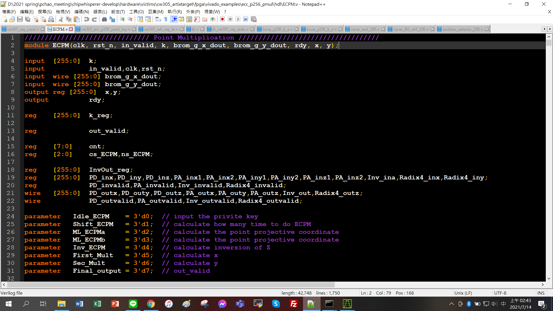
In the beginning, I just comment out curve_mul_256 U_curve_mul_256 in the cw305_ecc_p256_pmul_top.v and replace with my ECPM.v
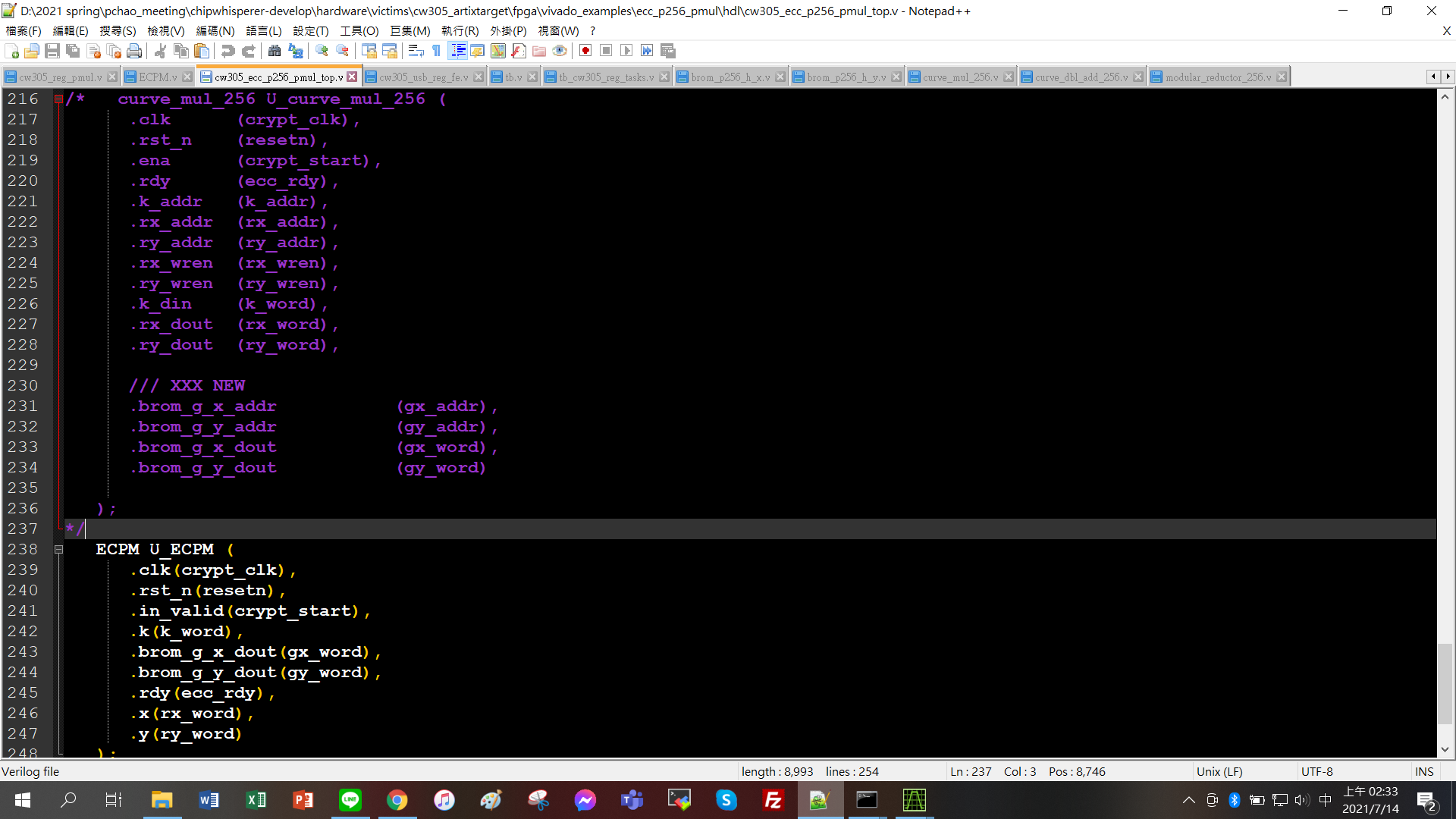
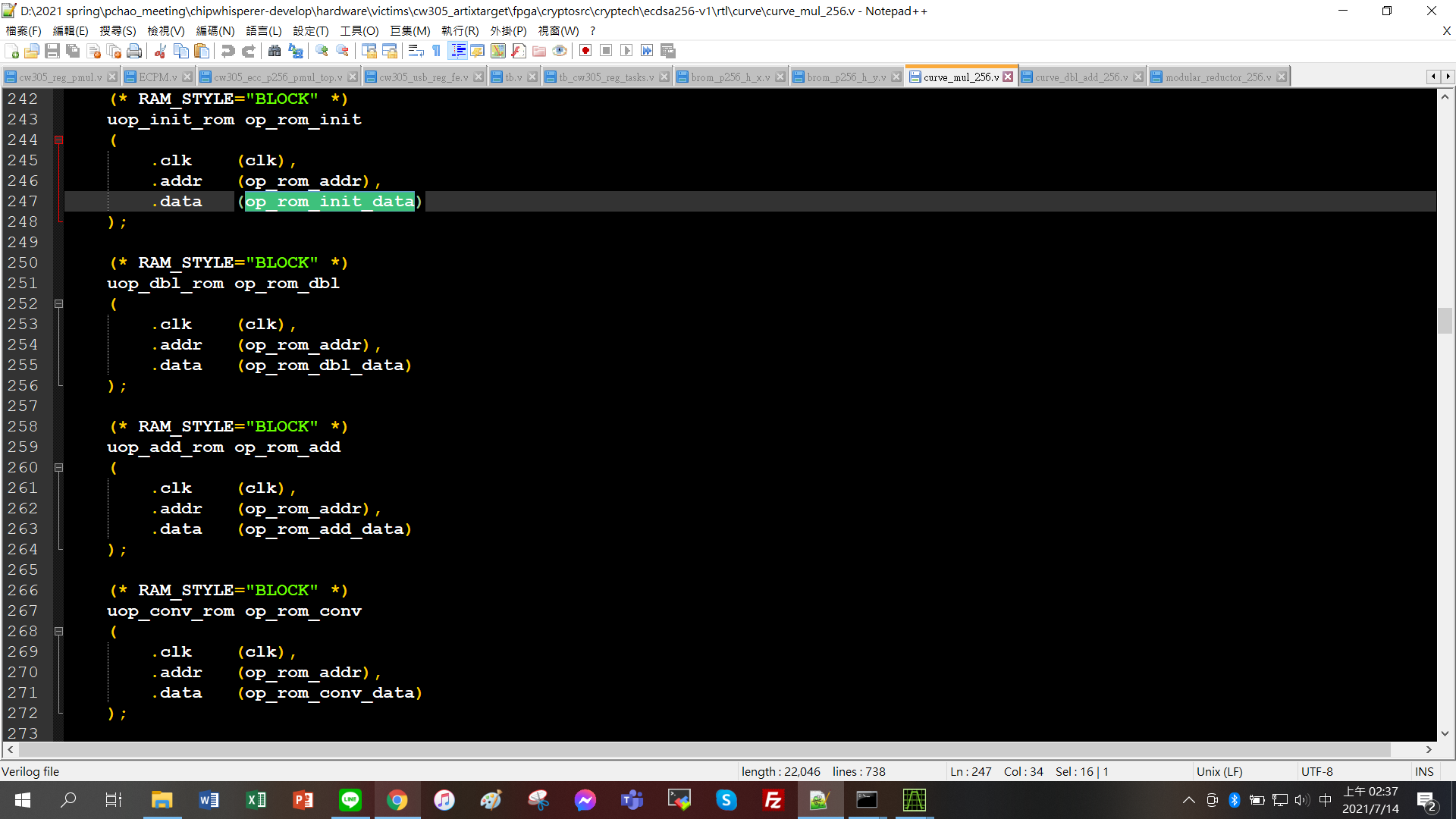
But I notice that there are a lot of bram declared in the curve_mul_256.v
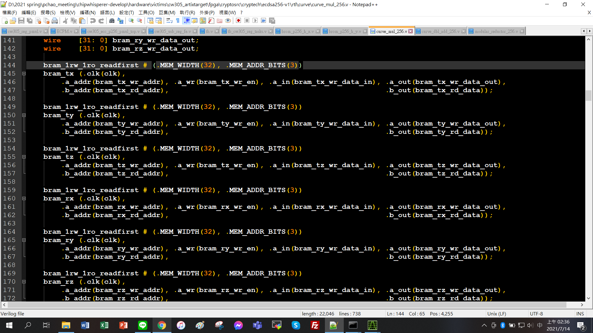
And in my design ECPM.v only use register to save my data, I think that’s why I can’t get the value through fpga? Is it correct?
And if I noticed that the bram width in the curve_mul_256.v is 32 bits, it means the computation of the ecc encryption in the curve_mul_256.v is 32 bits once?
Beause in my design I directly use 256 bits data to do the ecc encryption, this is my ecc algorithm verilog code register declare:
I want to ask about if the previous question(the bram cause) is correct, and I need to add bram to my design to save the computation data, should I use 32 bits width bram?Or I can use 256 bits for my design?
Thank you
Oscar
The use of BRAMs and the internal data path width are implementation choices which are completely irrelevant to a functionally correct implementation.
Jean-Pierre
1 Like