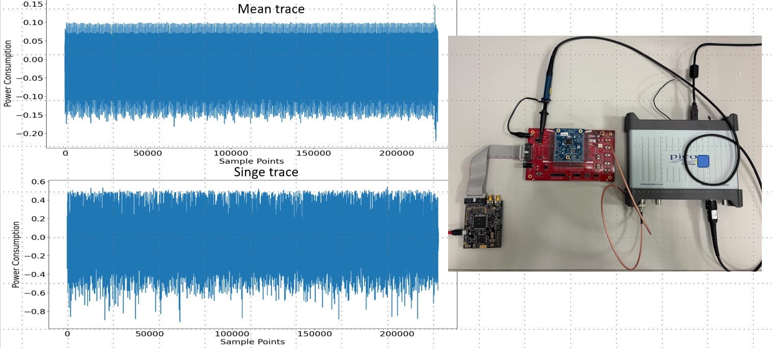
I am using the CW308 UFO board with an STM32F415 MCU, targeting a working frequency of 7.37 MHz. I record the power traces using an external PicoScope 6000 series oscilloscope. From the averaged power trace, I can roughly observe 32 peaks, but individual traces are very noisy. This high level of noise makes it difficult to train deep learning models effectively. Are there any aspects I should pay special attention to, thanks?
The first thing I’d check is whether this corresponds to the complete target operation?
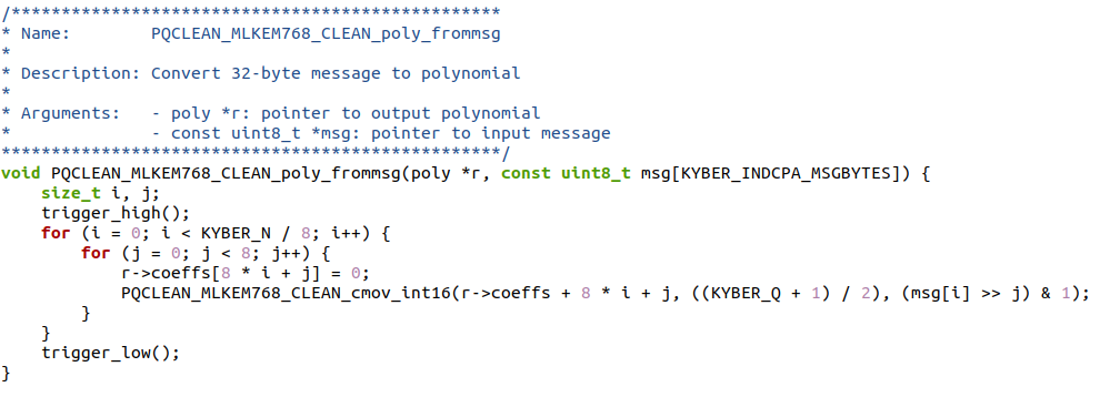
That’s right. I’m capturing power traces from a segment of the ML-KEM implementation. I placed the trigger before and after the target algorithm, and I can confirm that the loop runs 32 times, which corresponds to the 32 peaks in the power trace. However, each individual power trace contains a lot of noise.
This may be an issue with the STM32F4’s internal regulator; read here to see what you can do to overcome this.
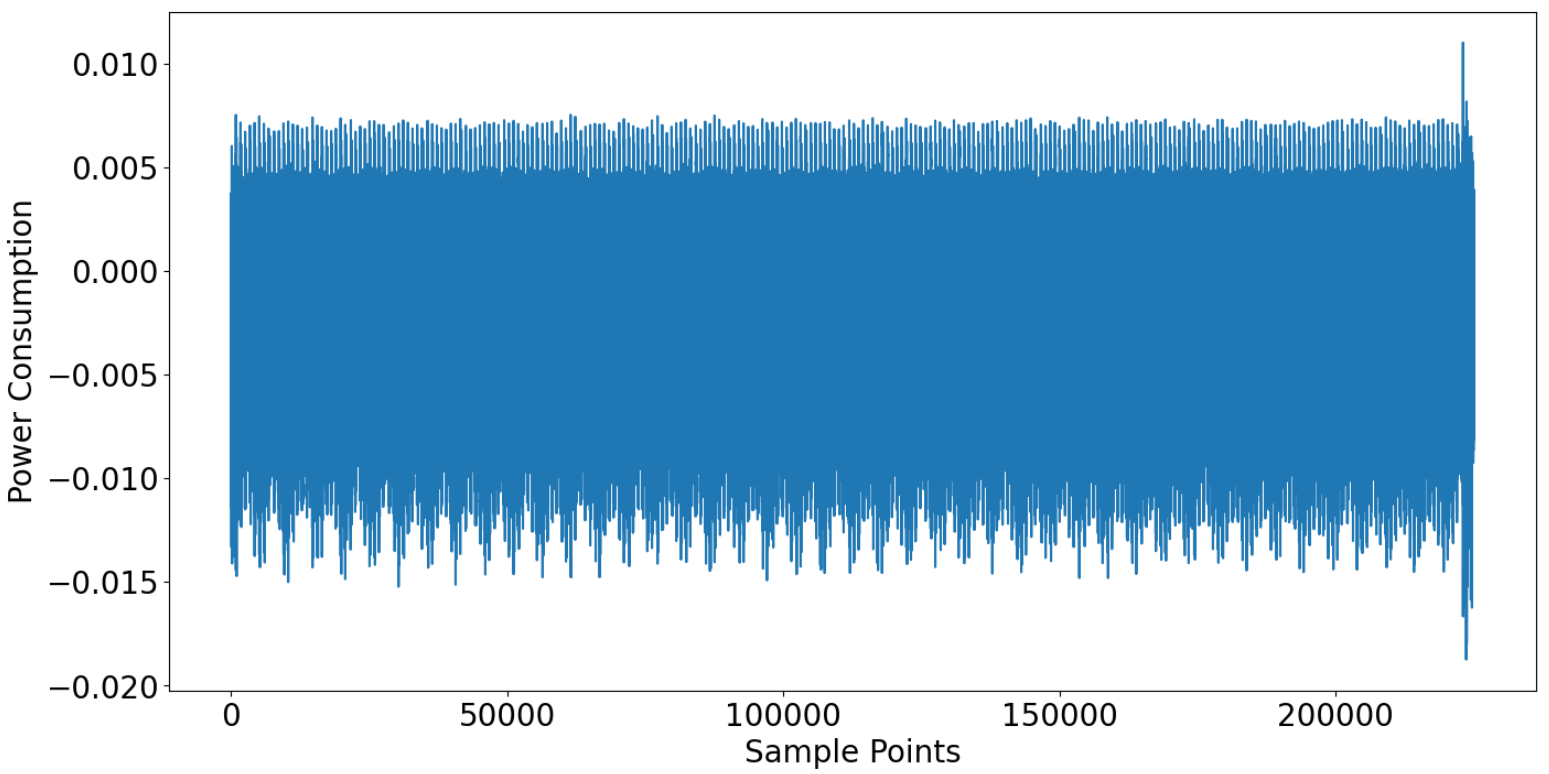
I understand. I would like to try using the External Voltage Regulator for the experiment. Could you please tell me how to configure the switches inside the black box in the CW308 image?
Also, I tried moving the red jumper on J14 to the right side**. How can I measure the voltage of VADJ (which test point should I use) to make sure the External Voltage Regulator is set to 1.2V?
thanks!
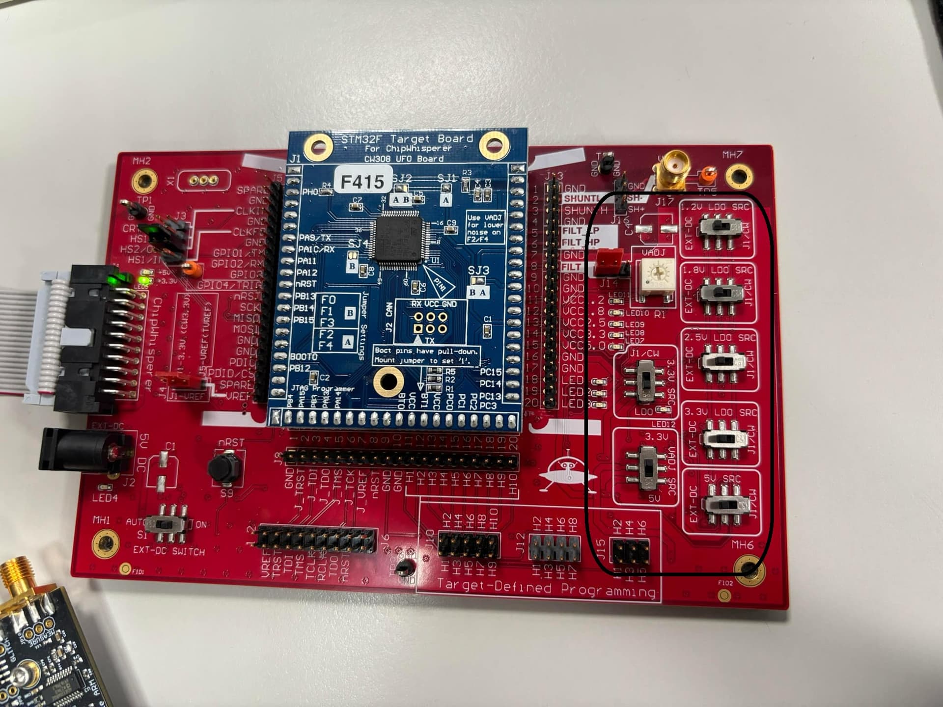
First ensure you have the 1.2V and 3.3V supplies; in your case it looks like you’re powering the target from the 20-pin connector, so set the 1.2V and 3.3V LDO SRC switches to J1/CW.
Then set the VADJ SRC switch to 3.3V.
Before setting J14 to the right, measure the VADJ voltage on the right-most pin of J14. Make sure it doesn’t exceed your target’s maximum recommended 1.2V supply voltage (or you risk killing the chip).
Then move J14 to the right (as shown here).
Hi, I followed your suggestion to set the 1.2V and 3.3V LDO SRC switches to J1/CW. And set the VADJ SRC switch to 3.3V.
Also I confirmed that J14’s voltage is 1.24V, then move J14 to the right.
However, the following error appears:
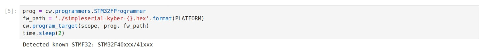
So I switched the 3.3V SRC over to J1/CW, and now the ChipWhisperer functions normally, as shown in the figure.
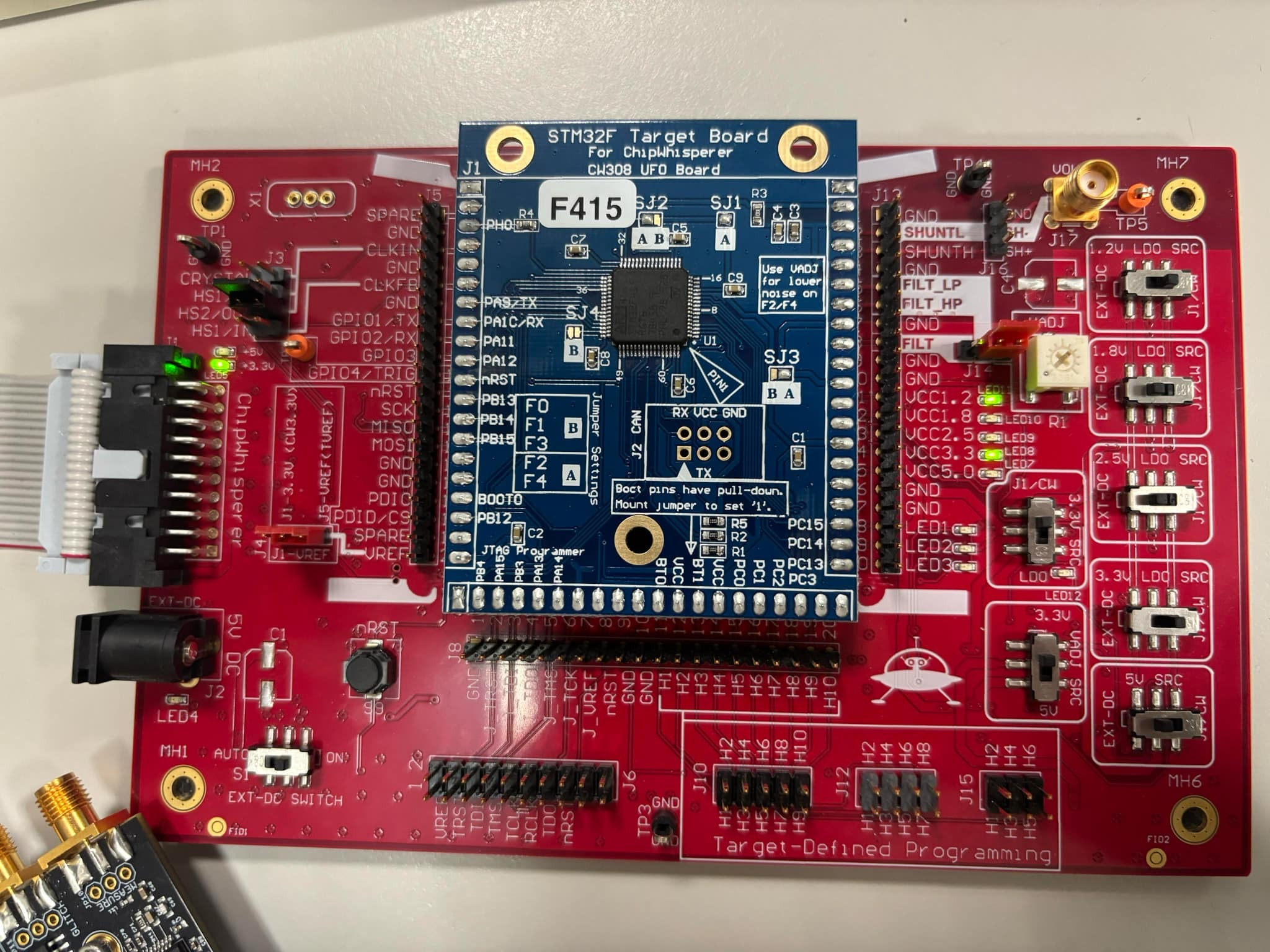
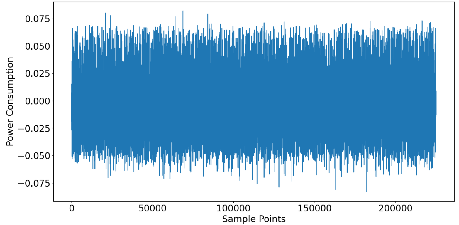
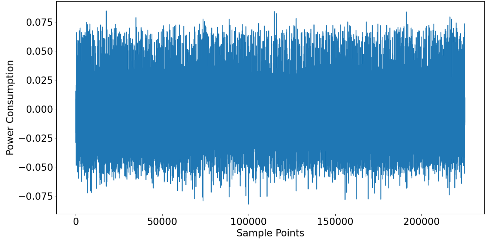
Based on my experimental results, there isn’t much difference in the power traces measured using the cw308’s external regulator compared to those measured using the MCU’s internal regulator.
The images are (in order):
- A single power trace using the internal regulator
- A single power trace using the external regulator
- The averaged power trace using the internal regulator
- The averaged power trace using the external regulator
thank you<3
Or could it be that the issue isn’t with the internal regulator?
Some noise will always be present. I would get some traces using one of our tutorials, capturing with the CW-lite and a different target like the STM32F3 to remove the voltage regulator from the equation. You can then compare with our saved traces (with the “simulated” notebooks). You can also see whether e.g. our CPA attack succeeds with the default number of traces.
If that looks alright I would then keep the same setup and add the picoscope, to compare CW-lite traces to picoscope traces.
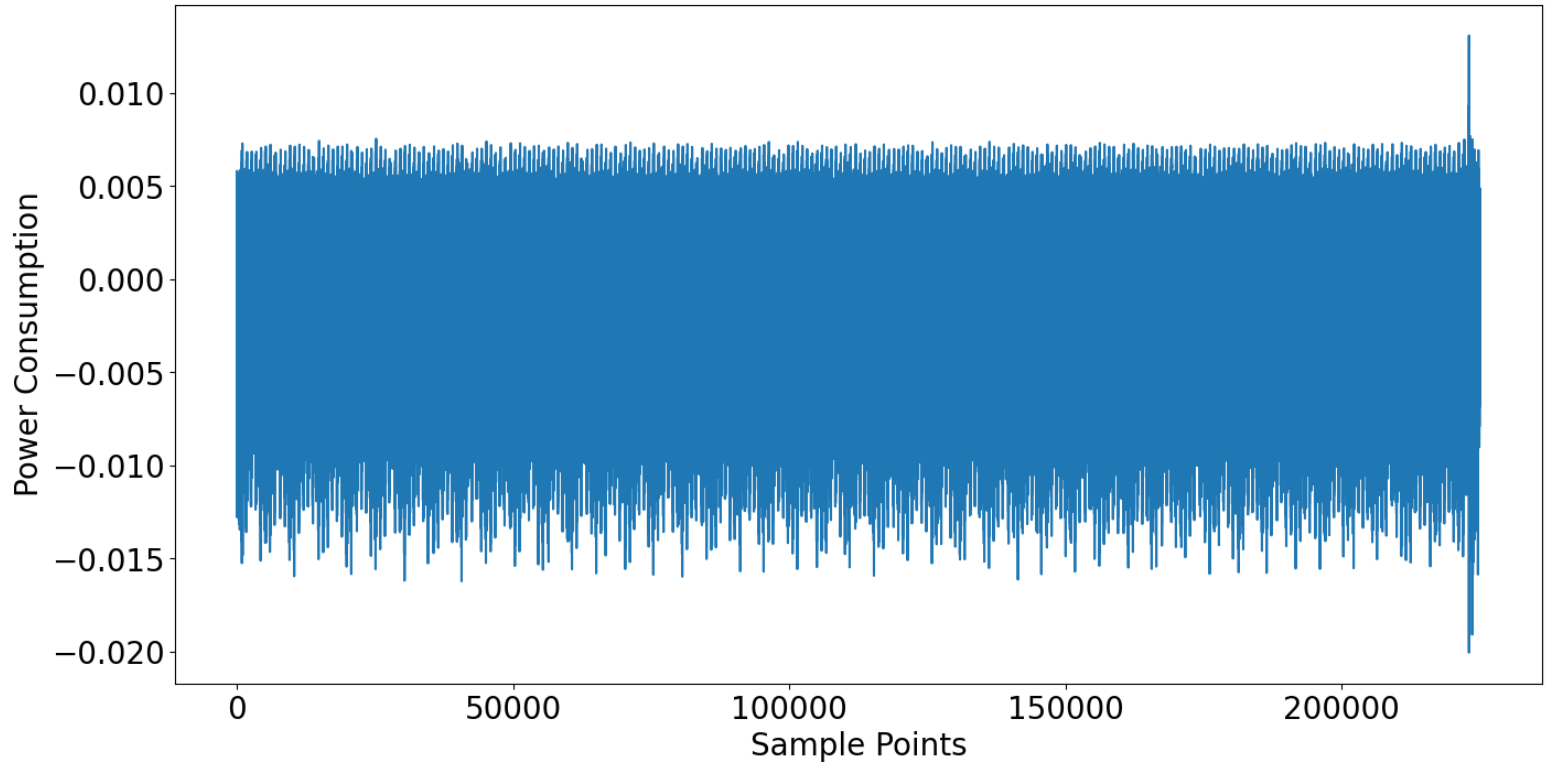
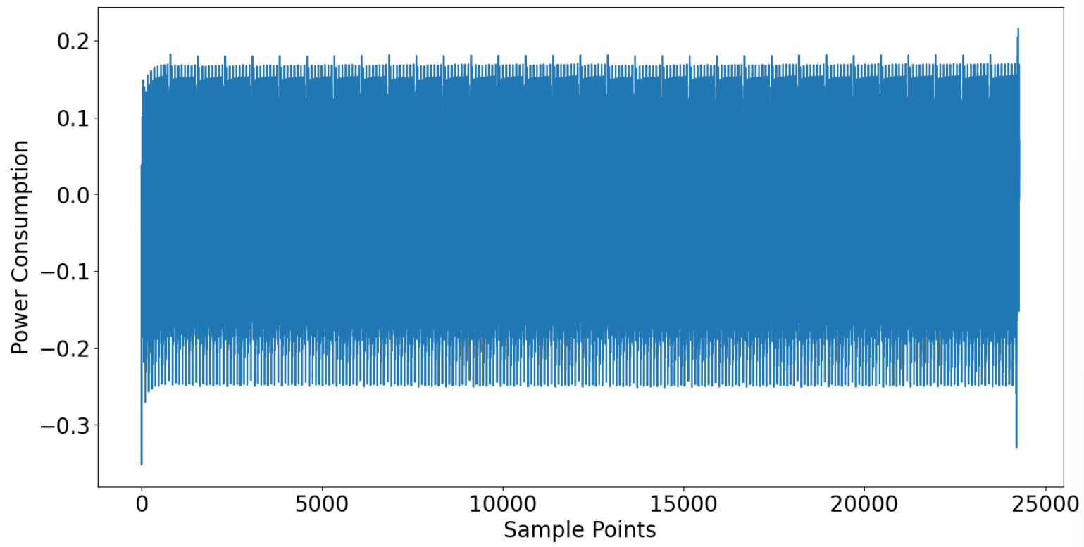
Unfortunately, I used the ChipWhisperer Lite to capture power traces from the CW308, and I also tried comparing the results using both internal and external regulators. However, the results are roughly as shown in the figure below.
single trace
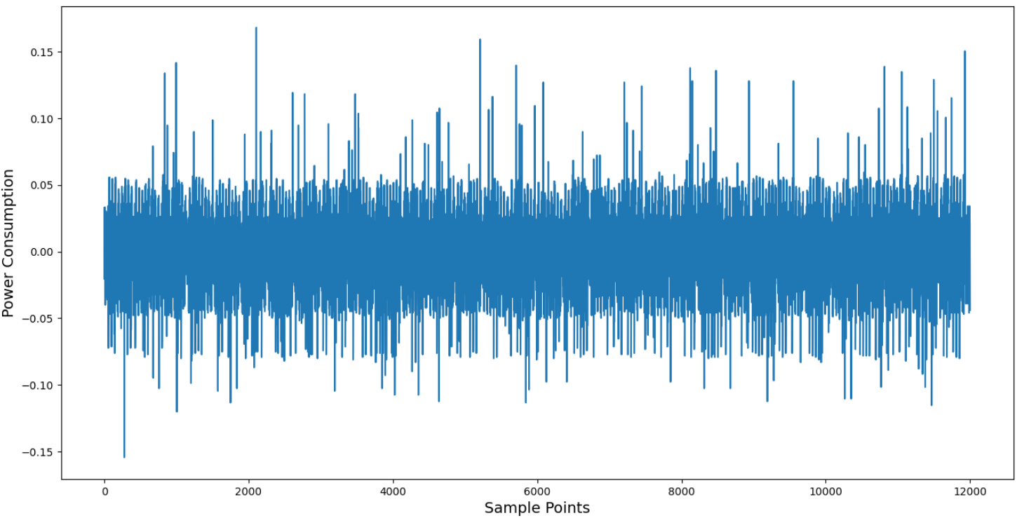
mean of 2000 trace
From the mean trace, the values range between 0.05 and -0.06, but some single power traces have very large peaks.
Do you have an STM32F3 to try, as I outlined in my previous post?
It’s astonishing! Just as you mentioned, it indeed appears to be an issue related to the STM32F4’s internal voltage regulator.
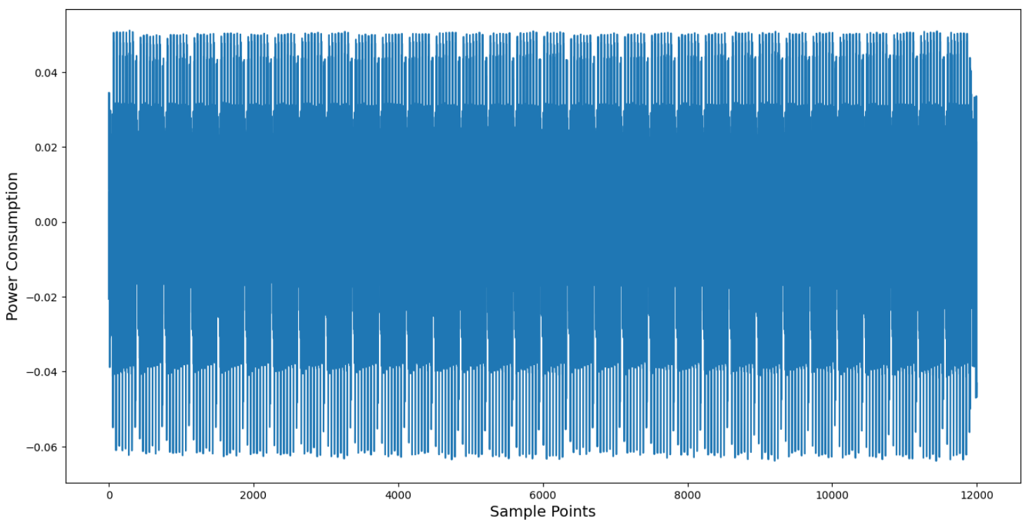
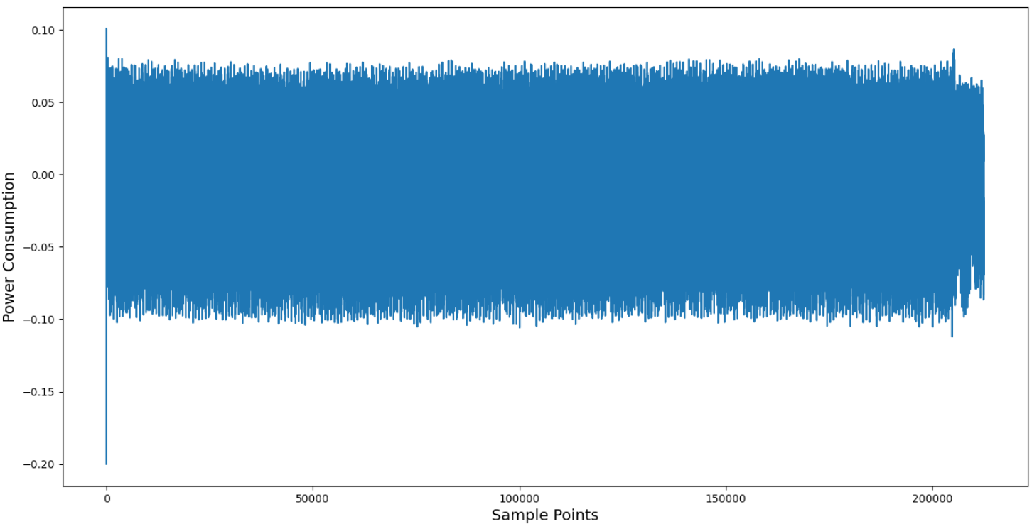
I used an STM32F303 MCU and measured power traces using ChipWhisperer Lite. In the single power trace, you can clearly see approximately 32 peaks, and there are no particularly prominent spikes, as shown in the image below.
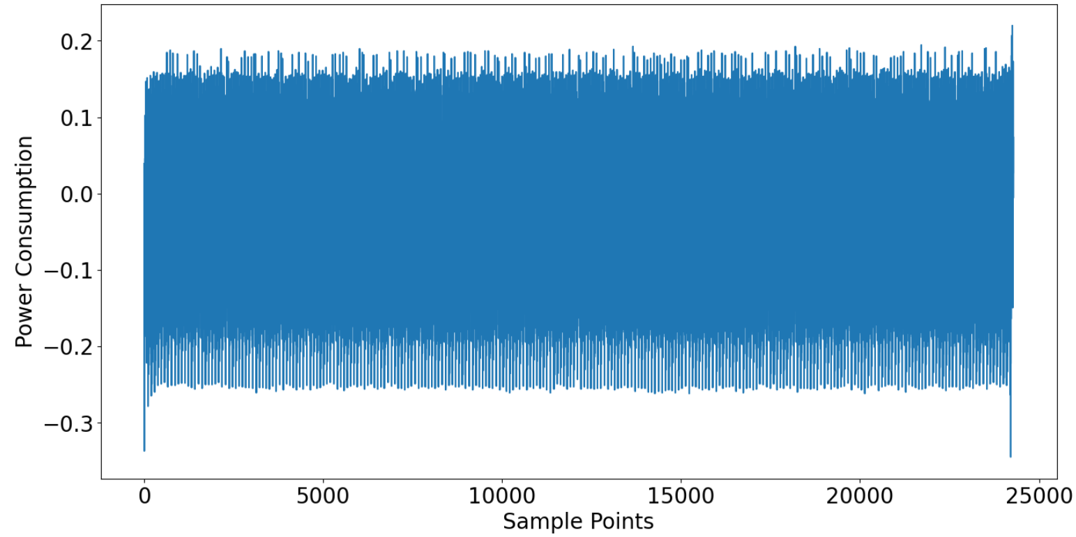
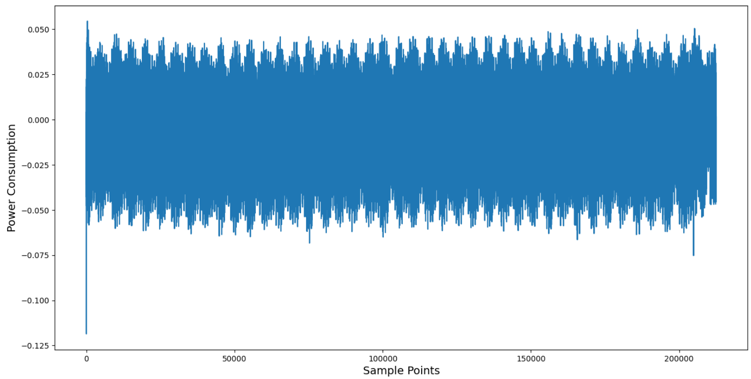
Additionally, I also performed measurements using a PicoScope. Compared to the ChipWhisperer Lite, there is slightly more noise present. The resulting single and averaged power traces are shown below.
However, since STM32F4 is currently the most common choice (which is also why I initially chose it), I set the VADJ to 1.24V, but it had no effect, and the internal voltage regulator was still triggered. Could you please explain why this happens?
1.24 is likely not high enough to disable the regulator.
You can search the forum to learn about others’ experiences with this target, for example CW308T-STM32F4 weird spikes in power trace
Keep in mind that some targets are simply noisier than others, and that noise is just part of life in this field.