Hi I’m trying to run the notebook from here, cw340-luna-board/jupyter/CW340_AES_test.ipynb at main · newaetech/cw340-luna-board · GitHub
I am able to upload the image, get adc lock, run the capture.
print(scope.clock) right before the capture (with CLOCKS_FIXED set to True):
clkgen_src             = extclk
clkgen_freq            = 10000000.0
adc_mul                = 20
adc_freq               = 200000000.0
adc_rate               = 200000000.0
freq_ctr               = 10000488
freq_ctr_src           = extclk
clkgen_locked          = True
adc_phase              = 13.3333333333333334
extclk_monitor_enabled = True
extclk_error           = False
extclk_tolerance       = 1144409.1796875
print(scope.errors) after the capture:
sam_errors      = False
sam_led_setting = Default
XADC errors     = False
ADC errors      = gain too low error,
extclk error    = False
trace errors    = False
The average PGE after a run is around 70.
The extclk_tolerance seems way off, but I tried with scope.extclk_tolerance=10, with the same result. The ADC error is also suspicious. I also tried with CLOCKS_FIXED=False with no luck.
JP9 is set to top position (3.3V)
JP5 is in bottom position (1-3)
J23+J24 are connected with a ribbon cable.
The husky is connected from the high port to the amplified port (J7) on CW341, and the negative side has a shorting cap.
Is there any thing else I should be looking for?
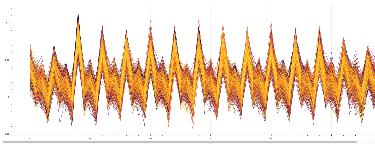
Plot of traces: