I’d like to trigger my oscilloscope whenever encryption starts to capture traces from the X4 pin on the CW305. After reviewing the cw305_top.v file from the ChipWhisperer example, I noticed that in the GOOGLE_VAULT_AES module, tio_trigger is connected to aes_busy. According to main.xdc, tio_trigger is routed to the T14 pin.
If I understand correctly, I should connect the EXT TRIG IN of my oscilloscope to the T14 pin on the CW305 and configure the oscilloscope to use EXT TRIG. Would this setup be sufficient to trigger the oscilloscope correctly?
I have a couple of follow-up questions:
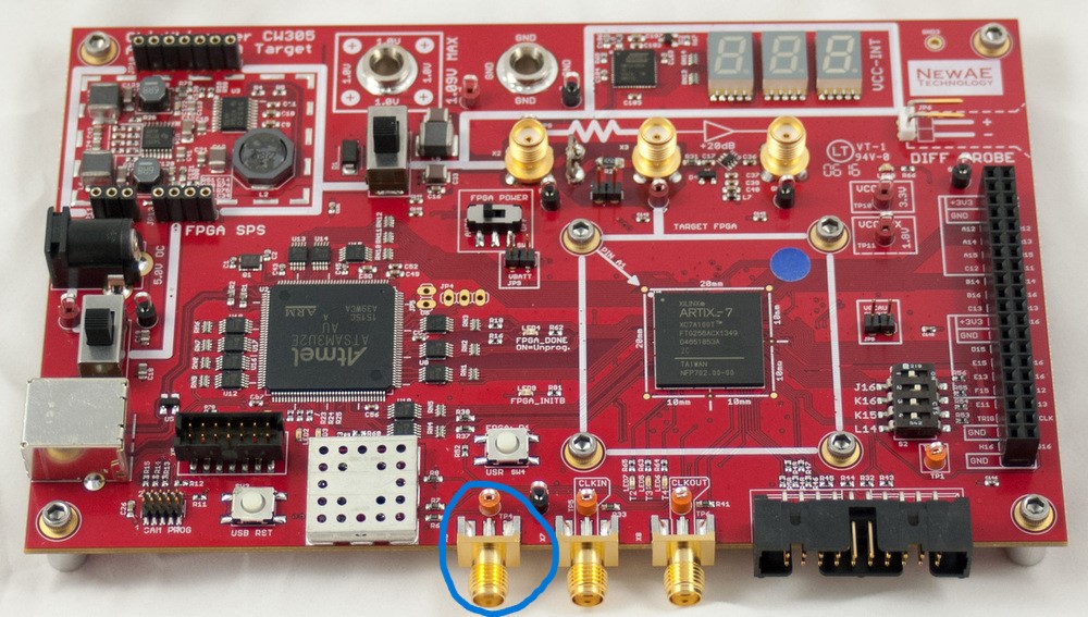
- Can you confirm the location of the T14 pin? I’ve attached an image of the board with the suspected T14 pin circled. Please verify if this is indeed the correct pin.
- Clarification on T1 vs. T14: I came across this forum post, which discusses using the T1 pin for EXT TRIG IN on the oscilloscope. Does this also apply when using
GOOGLE_VAULT_AESand themain.xdcfrom the ChipWhisperer example? I couldn’t find any definition for the T1 pin inmain.xdc, so would I need to add it manually as suggested in the forum? Or, if T14 works as expected, would it be better to stick with that?
Lastly, do you have any example configuration code that I can adapt to set up my oscilloscope? I’d like to:
- Configure EXT TRIG,
- Set the memory depth for trace capture,
- Fetch captured data from the oscilloscope’s memory,
- Convert the data for storage in a ChipWhisperer project for the attack simulation phase.
Thank you in advance for your assistance!